


Intel NetStructure
®
MPCBL0001 High Performance Single Board Computer 81
Technical Product Specification
Connectors
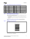
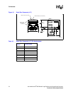
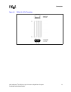
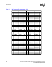
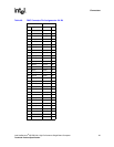
4.2.5 PMC Connectors (J25, J26, J27)
There are three 64-pin connectors that make up the PMC card connection:
MOLEX Part Number: 71439-0864
These connectors and pinouts are defined by the following industry standard specifications:
• Draft Standard Physical and Environmental Layers for PCI Mezzanine Cards: PMC IEEE
(MMSC) P1386.1/Draft 2.3, October 9, 2000
• Draft Standard for a Common Mezzanine Card Family: CMC IEEE (MMSC) P1386/Draft 2.3,
October 9, 2000
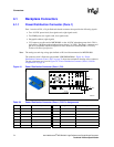
The PMC slot is available at the front panel. See Figure 13, “MPCBL0001 SBC Connector
Locations” on page 70 for their positions on the board. Pin assignments are listed in Table 45,
“PMC Connector Pin Assignments - 32 Bit” on page 82 and Table 46, “PMC Connector Pin
Assignments - 64 Bit” on page 83.
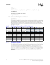
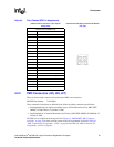
Table 44. Fibre Channel SFP Pin Assignments
USFibre Channel Connector (J34, J35) Pin
Assignments
Fibre Channel SFP Optical Transceiver Module
(J34, J35)
Fibre Channel CONNECTOR
Pin # Signal Name
1 Transmitter Ground
2 Transmitter Fault (not supported)
3 Transmitter disable
4 Module Definition 2
5 Module Definition 1
6 Module Definition 0
7 Rate Select
8 Loss of Signal Indication
9 Receiver Ground
10 Receiver Ground
11 Receiver Ground
12 Receiver Inverted DATA Out
13 Receiver Non-Inverted DATA Out
14 Receiver Ground
15 Receiver Power Supply
16 Transmitter Power Supply
17 Transmitter Ground
18 Transmitter Non-Inverted DATA In
19 Transmitter Inverted DATA In
20 Transmitter Ground