


Intel NetStructure
®
MPCBL0001 High Performance Single Board Computer 53
Technical Product Specification
Hardware Management Overview
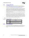
3.10 Interrupts and Error Reporting
3.10.1 Device Interrupts
The Low Voltage Intel
®
Xeon™ processor and E7501 chipset (MCH, ICH3, P64H2) utilize a
mechanism for delivering interrupts that is slightly different from, though fully compatible with,
previous IA-32 system platforms. The change affects only the delivery mechanism and no changes
are required to existing software.
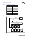
This new delivery mechanism transfers the equivalent APIC messages across the system bus
structure rather than using a sideband channel as in the case of the APIC serial bus. There is no
longer an APIC bus connection to the processor. This new mechanism improves the interrupt
message transfer speed to the processors, thus reducing latency. It also simplifies the flushing of
buffers that is required when data is buffered between the I/O subsystem and memory. Since
interrupt messages are no longer communicated across a sideband channel, these transfers are now
visible to the chipset. The interrupt message transactions themselves can now initiate buffer
flushing to ensure all data within the I/O and memory subsystems is coherent.
As before, the LINT[1:0] connections to the processors remain for compatibility with the old PC
industry standard, legacy interrupt architecture (8259 controllers). In addition, the P64H2 PCI
bridge devices include an interrupt output (BTINTR#), which can be routed into the legacy
interrupt controller to facilitate booting from devices residing on the far side of such PCI bridge
devices. Once the boot process is complete and the APIC interrupt system is enabled, devices no
longer need to share interrupts; This improves interrupt system performance.
The BIOS initializes and enables both the 8259 and APIC but masks all APIC interrupts in the
redirection table. This is so the SBC operates in legacy interrupt mode. The BIOS does not operate
in APIC mode at any time. An APIC-aware OS disables the 8259 and unmasks the APIC interrupts
to switch to APIC mode.
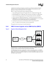
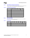
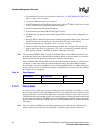
Table 22 displays the interrupt connections provided by the MPCBL0001 SBC. Actual interrupt
vector assignments and routing to legacy interrupts as necessary is under BIOS and/or OS control.
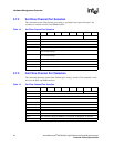
Table 22. Interrupt Assignments (Sheet 1 of 2)
Legacy Interrupt IRQ assigned
Master 8259
Internal timer0 output 0
Slave 8259 INTR output 2
Serial Port A 3
Slave 8259
Internal RTC 0 (8)
Primary IDE 6 (14)
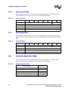
PCI Device Interrupt IRQ assigned
HI-A ICH3
Super I/O SERIRQ
USB 1.1 controller #1 PIRQA#
IPMC_SYSIRQ# PIRQB#