58 Intel NetStructure
®
MPCBL0001 High Performance Single Board Computer
Technical Product Specification
Hardware Management Overview
1. The reset button is pressed (see Note below). See Section 14, “MPCBL0001NXX SBC Front
Panel” on page 71 for its location.
2. A processor shutdown special cycle occurred.
3. An INIT command from Port 92h I/O register (refer to the Intel
®
82801CA I/O Controller Hub
3 (ICH3-S) Datasheet for information about this register).
4. An INIT command from Port CF9h I/O register.
5. A keyboard reset command (ICH3 RCIN# signal asserted).
6. The IPMC may also directly assert the INIT signal; WDT #1 expires and is configured for a
soft reset.
7. Processor BIST is enabled and a hard reset is initiated from the Port CF9h register. This asserts
the INIT signal but is not classified as a soft reset since CPU reset is also asserted.
8. OS reboot commands (eg: "shutdown -r now" or "reboot" in Linux).
9. A processor INIT may also be initiated through an APIC “init” message. This message may
target a specific processor or all processors. This “init” is an internally generated event (No
INIT signal is asserted) so the IPMC is unable to detect this occurrence.
Note: The reset button (RESET_PB#) is an input to the IPMC. There are also IPMI commands to reset
the board and change power states through the software. However, the reset button is a last resort
because the user must be physically present at the chassis to reset the board.
After a Soft Reset/CPU Init, the BIOS code executes and determines if the reset is a warm boot or
a cold boot. A warm boot restarts the system and keeps memory above the 8 MByte boundary
intact. During a warm boot the MCH is not reset, allowing DRAM refresh to continue during and
over the soft reset event. A cold boot sets the state of all peripherals to the same state they would be
in if a hard reset were triggered.
3.12.4 Warm Boot
A warm boot occurs when the processor is booting after a soft reset request. To qualify as a warm
boot, the reset counter located at 40h:D0h must be non-zero (by default, the reset counter and reset
flag are initialized to 10 and 1234h by BIOS after a cold boot.) Execution starts at the reset vector.
The BIOS initializes and configures all devices except for memory. Memory contents remain intact
except for the first 8 MBytes. The BIOS uses the first 8 MBytes during POST, but does not modify
the reset flag or the reset counter. MCH is not reset, allowing DRAM refresh to continue during the
warm boot.
Note: On every warm boot, BIOS automatically decrements the reset counter by one. When the reset
counter reaches zero and the soft reset is initiated, a cold boot occurs instead of warm boot.
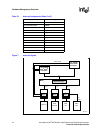
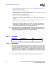
Table 24. Reset Request
Reset Request Signal Activated Type
Hard Reset Full reboot
Soft Init Partial reboot


