


40 Intel NetStructure
®
MPCBL0001 High Performance Single Board Computer
Technical Product Specification
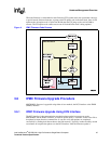
Hardware Management Overview
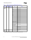
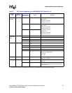
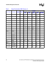
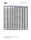
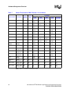
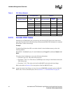
Table 8 shows the PCI mapping of the component subsystem of the baseboard.
NOTE: This table is for MPCBL0001F04 boards. Bus Devices 5 and 7 do not exist for MPCBL0001N04 boards.
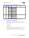
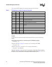
Example:
To decode the device and function number from the System Event Log, refer to the following
method.
0144 05/26/04 15:24:42 4023 13 Critical Interrupt 07 PCI PERR 6f [a4 04 08]
• Event data 1 = a4
Comments: FromTable 3 on page 31, event data 1, bit 3:0 is referring to PCI-PERR
• Event data 2 = 04.
Comments: From Table 3, event data 2, bit 7:0 is referring to Bus number 4.
• Event data 3 = 08 = 00001000
Comments: FromTable 3, event data 3, bit 7:3 is equivalent to 1 which refers to Device number 1.
Event data 3, bit 2:0 is equivalent to 0 which refers to Function number 0. From Table 8 above, the
PCI parity error was on the interface of the Gigabit Ethernet Controller (Port A).
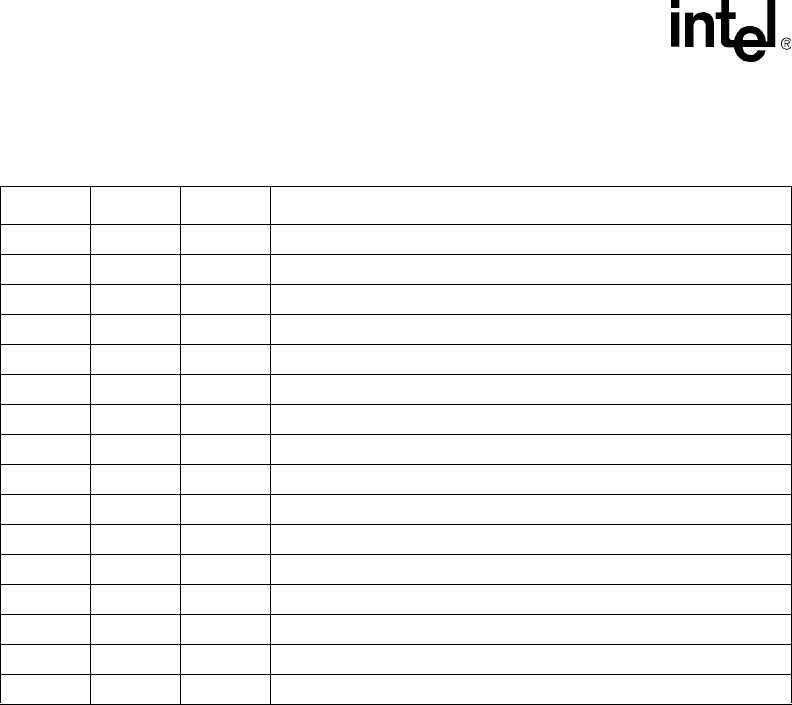
Table 8. PCI Mapping for Hardware Component Subsystem
Bus Device Function Hardware Component Subsystem
000E7501 MCH Bridge
001MCH <-> ICH3
0 2 0 82870P2 PCI-X Bridge (PMC and Gigabit Ethernet Controller)
030MCH <-> 82870P2 PCI-X Bridge (Fibre Channel Controller)
0 29 0 USB Controller
0 31 1 IDE Interface (hard disk drive)
0 31 3 IPMC Interface
2 29 0 PCI-X Bridge to Gigabit Ethernet Controller
210PCI-X Bridge to PMC Card
310PMC Card
410Gigabit Ethernet Controller (Port A)
4 29 1 Gigabit Ethernet Controller (Port A)
5 29 0 PCI-X Bridge to Fibre Channel Controller
710Fibre Channel Controller (Port A)
711Fibre Channel Controller (Port B)
0XFF - - PSB (processor-side bus) Error