


Intel NetStructure
®
MPCBL0001 High Performance Single Board Computer 25
Technical Product Specification
Features Overview
2.2.7 Onboard Power Supplies
The main power supply rails on the MPCBL0001 SBC are powered from dual-redundant -48 V
power supply inputs from the backplane power connector (P10). There are also dual redundant,
limited current, make-last-break-first (MLBF) power connections. See Figure 20, “Intel
NetStructure® MPCBL0001 Component Layout” on page 90 for their location.
2.2.7.1 Power Feed Fuses
As required by the PICMG 3.0 Specification, the MPCBL0001 SBC provides fuses on each of the
-48V power feeds and on the RTN connections as well. The fuses on the return feeds are critical to
prevent overcurrent situations if an ORing diode in the return path fails and there is a voltage
potential difference between the A and B return paths.
2.2.7.2 ORing Diodes and Circuit Breaker Protection
The two -48 V power connectors are OR’d together. A current limiting FET switch is connected
between the OR’d -48 V and the primary DC-DC converters. The FET switch provides three
functions:
• A mechanism to electrically connect/disconnect the SBC to/from the two -48 V inputs.
• A soft-on function.
• An over-current circuit breaker feature.
2.2.7.3 -48 V to +12 V Converter
This converter provides DC isolation between the -48 V and -48 V return connections and all of the
derived DC power on the MPCBL0001 SBC. Its output is connected to the SBC’s +12 V power
rail. The converter supplies a maximum of 9 A of current. The converter is enabled/disabled by the
onboard IPMC.
2.2.7.4 -48 V to +5 V/+3.3 V Converter
This converter provides DC isolation between the -48 V and -48 V return connections and all of the
derived DC power on the MPCBL0001 SBC. Its output is connected to the SBC’s +5 V and 3.3 V
power rails. The converter supplies a maximum of 9 A of +5 V current and 9 A of +3.3 V current.
The converter is enabled/disabled by the onboard IPMC.
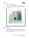
2.2.7.5 Processor Voltage Regulator Module (VRM)
The Voltage Regulator Module (VRM) provides core power to the two Low Voltage Xeon
processors. The input to the VRM is connected to the +12 V power rail.
See Figure 20, “Intel NetStructure® MPCBL0001 Component Layout” on page 90 for its location.