


44 Intel NetStructure
®
MPCBL0001 High Performance Single Board Computer
Technical Product Specification
Hardware Management Overview
3.4 E-Keying
E-Keying has been defined in the PICMG 3.0 Specification to prevent board damage, prevent
misoperation, and verify fabric compatibility. The FRU data contains the board point-to-point
connectivity record as described in Section 3.7.2.3 of the PICMG 3.0 Specification.
Upon management power-on, the firmware sets the Fibre Channel ports to front panel by default.
When the board enters M3 power state, the shelf manager reads in the board point-to-point
connectivity record from FRU and determines whether the board can enable the Fibre Channel
ports to the back plane. Set/Get Port State IPMI commands defined by the PICMG 3.0
Specification are used for either granting or rejecting the E-keys.
If user Fibre Channel selection is to the front, the firmware maintains the Fibre Channel ports to the
front panel regardless of the shelf manager’s granting or rejecting of E-keys for the board.
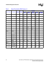
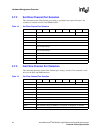
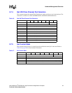
Table 12 on page 44, describes the:
• Connections to base and fabric interfaces on the MPCBL0001 board for E-keying purposes.
• Link descriptor list for the two Gigabit Ethernet channels connected to the base interface and
the two Fibre Channels on the fabric interface.
NOTE: Fibre Channel E-keying is only applicable to MPCBL0001FXX products.
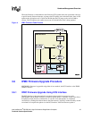
3.5 IPMC Firmware Code
IPMC firmware code is organized into boot code and operational code, both of which are stored in
a flash module. Upon an IPMC reset, the IPMC executes the boot code and performs the following:
1. Self test to verify the status of its hardware and memory.
2. Sets up the internal real-time operating system (RTOS).
3. Performs a checksum of the operational code.
Upon successful verification of the operational code checksum, the firmware will jump to the
operational code.
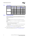
Table 12. Link Descriptors for E-Keying
No Link
Descriptor
Link
Grouping
ID
Link Type
Extension
Link Type Link Designator Link Desc
Value
Port 0 -
3 Flags
Interface Channel
Number
[31:24] [23:20] [19:12] {11:8} {7:6} [5:0}
1 Ethernet
Port 1
0 0000 00000001 0001 00 000001 0x00001101
2 Ethernet
Port 2
0 0000 00000001 0001 00 000010 0x00001102
3 FC Port 1 0 0010 00000010 1000 01 000001 0x00202C41
4 FC Port 2 0 0010 00000010 1000 01 000010 0x00202C42