


Intel NetStructure
®
MPCBL0001 High Performance Single Board Computer 63
Technical Product Specification
Hardware Management Overview
WDT #1 can also be configured to take various actions before timing out (for example, SMI, NMI,
nothing) or after timing out (for example, hard reset, power down, or power cycle). In addition, an
event can be logged into the SEL whenever the watchdog timer expires. If WDT #1 expires, the
IPMC is not reset. For more details on the watchdog timer commands and settings, see the IPMI
Specification version 1.5.
On power up, the initial state is that the IPMI WDT #1 is not running. Normally some code (BIOS
or OS level) must send the Reset Watchdog Timer command to start the timer running. The same
code sends a Set Watchdog Timer command first to set up the timer to a known state (see the IPMI
Specification for more details).
When WDT #1 times out, it logs an event into the SEL, provided that the “Don’t Log” flag is false
(see the IPMI 1.5 Specification for details). The SEL event also describes the timeout action taken.
If WDT #1 times out and causes a hard reset, the timer state is equivalent to the power-up state
(that is, not running; either BIOS or the OS must configure and start it). If the host processor is
reset (soft or hard) independent of WDT #1, the firmware disables the watchdog timer.
One of the actions BIOS takes very early in its code is to start the WDT #1 to monitor its boot
progress. When it finishes POST, the BIOS turns off WDT #1 during the OS load period.
WDT #1 parameters are altered according to BIOS control parameters, and WDT #1 is not running
when the OS first (re)starts. The BIOS sets WDT #1 to a length of time longer than the expected
POST time; therefore, BIOS does not actively strobe WDT #1. The flag that determines if a WDT
#1 reset must be hard or soft remains over any type of reset, since it is held in the microcontroller.
3.13.2 WDT #2
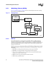
WDT #2 (implemented in a PLD) must be strobed by the IPMC firmware. If WDT #2 expires, it
isolates the SBC from the backplane IPMB buses and resets the IPMC. There is no method for the
processor to be explicitly notified that the IPMC is reset. Once the IPMC has reset, the main
processors can resume communication with the IPMC. The watchdog timer is set to trigger after 96
seconds, and the IPMC strobes it once a second.
WDT #2 is always running; that is, the counter is always counting. However, a PLD component
controls the IPMC reset and IPMB isolation associated with WDT #2 expiration, ignoring any
WDT event until the IPMC strobes/enables the LTC4300 IPMB interfaces.
3.13.3 WDT #3
WDT #3 is contained within the ICH3 device. This watchdog timer monitors the processor’s first
attempt to fetch an instruction after a power up or hard reset. If the processor has not fetched its
first instruction within the timeout period, the ICH3 resets the processors. Since the processor has
not begun any execution, the ICH3 uses a hard reset.