


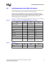
Intel NetStructure
®
MPCBL0001 High Performance Single Board Computer 51
Technical Product Specification
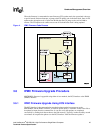
Hardware Management Overview
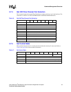
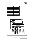
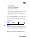
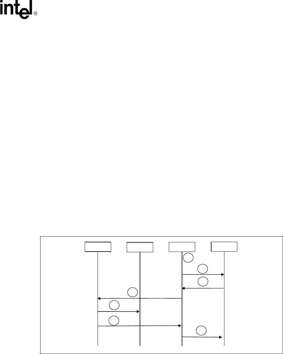
3.9 Hot-Swap Process
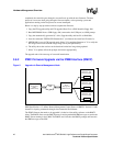
The MPCBL0001 SBC has the ability to be hot-swapped in and out of a chassis. The onboard
IPMC manages the SBC’s power-up and power-down transitions. The list below, along with
Figure 6, illustrates this process.
1. Ejector latch is opened. HOT_SWAP_PB# assertion. IPMC firmware detects the assertion of
this signal.
2. IPMC sends "Deactivation Request" message to CMM. M state moves from M4-> M5.
3. Board moves from M5 -> M6 if the CMM grants the request.
4. The IPMC's ACPI timer (3 minutes) starts if an ACPI-enable OS is loaded. Otherwise, it goes
to Step 7 below. The IPMC asserts 20 ms pulse on SMC_PWRBTN#.
5. The Power Button Status register (PWRBTN_STS) is set. It then asserts SCI/SMI# to the OS.
If ACPI OS is enabled, SCI interrupt handler on the OS is called. Interrupt handler clears
PWRBTN_STS bit. OS starts to perform a graceful shutdown.
6. ICH3 detects "LOW" on the ICH3_PWRBTN#. Asserts ICH3_SLP_S3# and ICH3_SLP_S5#
to IPMC. Upon detection of ICH3_SLP_S5# and ICH3_SLP_S3#, board transitions to Step 7
below. If ICH3 doesn't assert the signals, the board will transition to Step 7 below upon the
ACPI timer expiration.
7. The firmware deasserts payload power and sets the IPMI locked bit before it transitions from
M6 to M1 state.
Note: If the upper-level software moves the IPMC to M6, the same procedure is followed, starting with
Step 4.
Figure 6. Hot-Swap Process
ACPI-OS
IPMC
CMM
ICH3
1
4
5
6
2
3
7