


Intel NetStructure
®
MPCBL0001 High Performance Single Board Computer 19
Technical Product Specification
Features Overview
Note: Performance of the IDE interface may be impacted by the DMA mode and type of DMA transfers
used. Even though the BIOS automatically sets the DMA mode/type, the OS could downgrade the
DMA transfer mode. Check the operating system documentation to see what DMA mode is used
by default and whether it is possible to change to a higher performance DMA mode.
2.2.2.3 Intel
®
82870P2 64-bit PCI/PCI-X Controller Hub 2 (U14, U24)
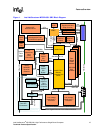
The two P64H2 devices provide the system’s high-performance PCI bus support. See Figure 20,
“Intel NetStructure® MPCBL0001 Component Layout” on page 90 for their locations. Each
P64H2 component supports two independent, 64-bit, PCI/PCI-X interfaces. 32-bit/33 MHz and 64-
bit/66 MHz PCI bus modes are also supported. Each PCI bus interface features:
• PCI-X 1.0 Specification compliance
• PCI Specification 2.2 compliance
• PCI-PCI Bridge Rev 1.1 compliance
• PCI Hot Plug 1.0 compliance
• I/O APIC supporting up to 24 interrupts (16 external pins)
• PCI peer-to-peer write capability between PCI ports
• SMBus target for Out-of-Band access to all internal PCI registers
Each of the two P64H2 devices (U14, U24) included on the MPCBL0001 SBC provides the bridge
to two independent PCI bus connections, as shown in Table 1, “P64H2 Interfaces” on page 19.
The two high-speed communications interfaces (Gigabit Ethernet and Fibre Channel) are located in
separate P64H2 devices to maximize data throughput. A single HI-2 hub link connection from the
P64H2 to the MCH provides a >1 Gbyte/s bandwidth back to memory and the processor System
Bus.
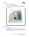
2.2.3 Memory (J8, J9, J10, J11)
Four DDR 266 DIMM sockets make up the memory subsystem. See Figure 20, “Intel
NetStructure® MPCBL0001 Component Layout” on page 90 for their locations. The MCH defines
two memory channels operating in parallel to logically create a 144-bit wide memory data path.
ECC is generated and checked across 128 bits of data, allowing for significant improvement in
error correction.
Due to this architecture, DDR DIMMs must be installed in matched pairs. Memory DIMM
configurations ranging from 512 MBytes to 8 GBytes in 512 MByte increments are supported.
Table 1. P64H2 Interfaces
P64H2 Device Interface
U24 PCI-X interface to the optional dual Fibre Channel controller
U14
• PCI-X interface to the dual Gigabit Ethernet controller
• 64-bit/66 MHz PCI bus for a plug-in PMC card