


OCPRF100 MP Server System Technical Product Specification
Revision 1.0
94
8.2.7.3 Fault LEDs
The hot-swap controller is responsible for turning the drive fault LEDs on or off according to the
states specified via commands received through SAF-TE and the IPMB. The drive fault LEDs are
yellow and serve to indicate failure status for each drive. The LEDs are physically located on the
LVDS SCSI backplane, and are driven from the backplane.
During initialization, the microcontroller flashes the LEDs for 2 seconds to signal POST comple-
tion successfully.
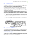
8.2.8 IPMB (I
2
C bus)
The Intelligent Platform Management Bus(IPMB) is a system-wide I
2
C server management bus.
It provides a way for various system components to communicate independent of the other sys-
tem interfaces (e.g., the PCI bus or the processor/memory bus). The I
2
C bus controller is inte-
grated into the microcontroller.
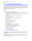
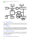
8.2.9 Temperature Sensor
A Dallas* DS1621 temperature sensor device is connected to each microcontroller on a “private”
I
2
C bus. This device is used to monitor the drive bay temperature. The temperature may be read
via SAF-TE and IPMB commands. In addition, settable temperature thresholds are provided via
IPMB commands. The hot-swap controller (HSC) can be configured to issue an event message
on the IPMB when the temperature threshold is crossed.
Microcontroller programming implements the private I
2
C connection by explicitly setting and
clearing appropriate clock and data signals, to emulate an I
2
C-like interface to the sensor.
8.2.10 Serial EEPROM
The AT24C02N* provides 256 bytes of nonvolatile storage. This is used to hold the serial num-
ber, part number, and other field replaceable unit (FRU) inventory information and miscellaneous
application code used by firmware about the backplane.
8.3 Board Functions
This section describes functioning parts as required by the SCSI Accessed Fault-Tolerant Enclo-
sures Interface Specification and SCSI Command Set For Enclosure Services Document Speci-
fication. In addition to these requirements, the board is capable of downloading code via IPMB to
update the Flash executable code. The backplane functions begin at power up.
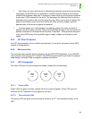
8.3.1 Reset
8.3.1.1 Cold Reset
At power up, all logic on the backplane is held in reset until the power supplies are stable. Two
sources of power-good signaling are used. The first is the PWR_GOOD signal from the power