


OCPRF100 MP Server System Technical Product Specification
Revision 1.0
10
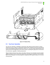
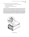
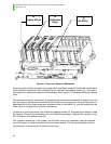
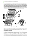
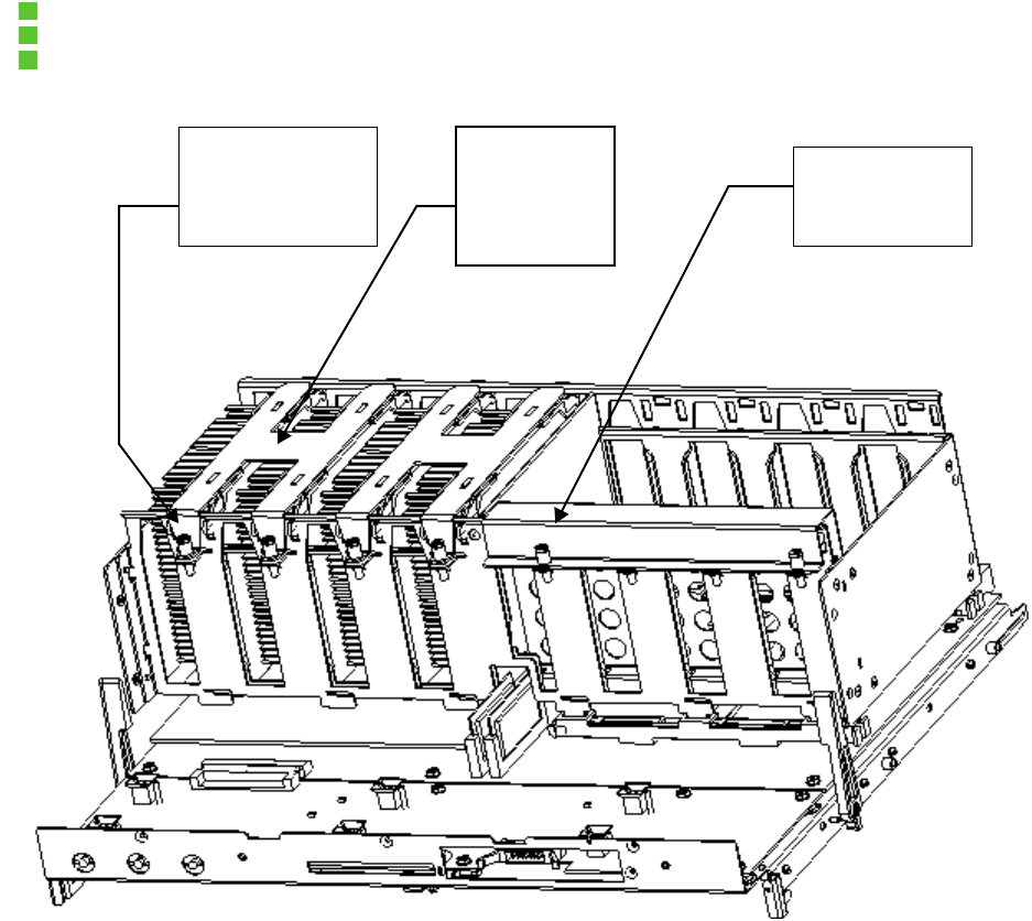
Figure 2-7: Processor Retention Mechanism
A processor/termination card pair is secured with a hold-down strap (B) that hooks into the back
of the retention mechanism and is fastened at the front with two captive screws (A). (The reten-
tion strap is for a pair of processors or terminators). See Figure 2-7: Processor Retention Mecha-
nism.
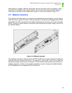
The processor retention mechanism is secured to the mezzanine boards with the same four lock
bars that secure the mezzanine boards to the Profusion carrier board. In the event the server is
populated with only a single processor mezzanine card, an air baffle (C) must be installed on the
vacant side of the processor retention mechanism.
To remove or add a processor, first release the captive screws (A), then swing the retention strap
(B) upward. Remove the terminator card, and install the processor. Replace the retention strap
(B), and tighten the captive screw (A).
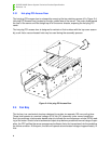
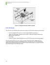
Due to space restrictions in the system, the Profusion carrier tray assembly must be removed
from the chassis to install and service the mezzanine boards. The fan bay assembly must be
removed prior to removing the Profusion carrier tray.
A
Captive Screw
C
Air Baffle
B
Hold-down
Strap