OCPRF100 MP Server System Technical Product Specification
Revision 1.0
4
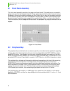
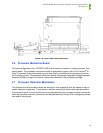
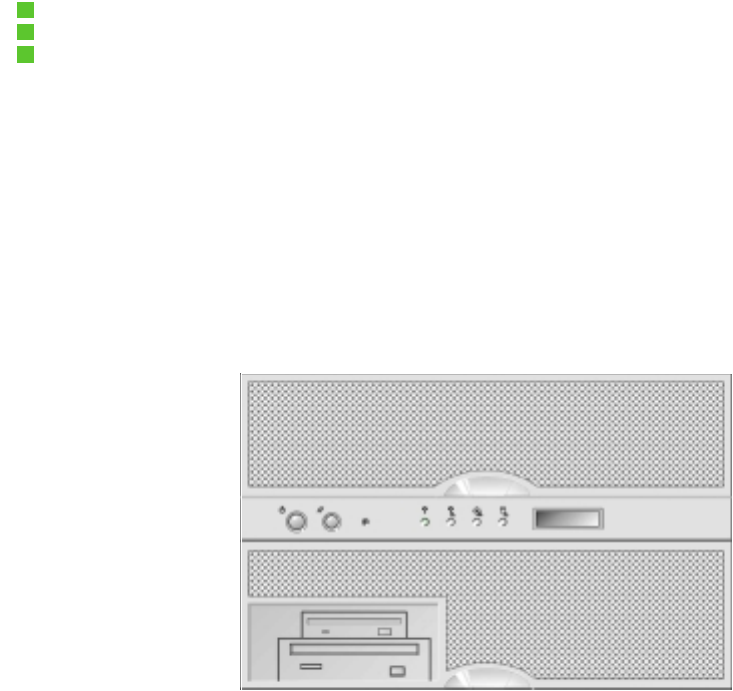
2.1 Front Panel Assembly
The front panel assembly consists of an upper and lower bezel. The bezels serve as cosmetic
pieces only, and can be integrator specific. Finger grips are provided to make it easy to remove
the bezels. Removing the bezels exposes the front side of the fan bay, the front panel controller
(FPC) switches (power, reset, and nonmaskable interrupt (NMI)), as well as the indicator lights
(power indicator, predictive power supply failure, predictive fan failure, and hard drive failure).
From this location, the hot-swap hard drives and/or the peripheral bay may be removed from the
system.
Figure 2-2: Front Panel
2.2 Peripheral Bay
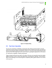
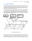
The peripheral bay is defined to be a customer specific, removable device capable of supporting
a floppy drive, dual hot-swap hard drives, and a low-voltage differential SCSI (LVDS) or single
ended SCSI device. The integrator has the option of defining the size and capacity of the hard
drives, as well as deciding whether the LVDS will support CD-ROM, tape, or other device. A sin-
gle ended SCSI channel is provided for support of a SCSI device, should the integrator so desire.
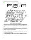
The peripheral bay is designed to be easily added and removed from the front of the server by
removing the front cover and four mounting screws. The peripheral bay connects to the
OPRF100 I/O carrier and the power supply via a blind mate board connector and cabling. The
blind mate board is located in front of the midplane board, on the left side of the server (when
viewing the server from the front). The blind mate connector connects to the peripheral bay’s
LVDS board upon insertion, thus connecting all peripheral devices to the I/O carrier.
The peripheral bay will contain a 1.4 MB floppy drive, space for a half-height 5 ¼ inch device
(typically a CD-ROM), and has two bays designed to accommodate either a 1-inch or a 1.6-inch
SCA hard drive.


