


OCPRF100 MP Server System Technical Product Specification
Revision 1.0
8
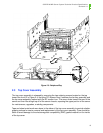
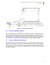
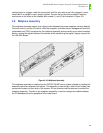
Fans are installed with the connector on the left side facing down. The cavities in the fan bay are
keyed to prevent a fan from being installed backwards.
The fan bay is installed after the Profusion carrier assembly is installed and completely seated
into the midplane. The fan bay is lowered into the chassis until it is seated on the flanges of the
Profusion tray. Two screw holes, one on each side, should now be aligned on the sides of the
chassis. Insert screws into these holes to secure the fan bay into the chassis.
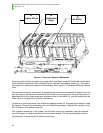
The fan bay cover is hinged at the rear and captivated by the system top cover assembly. Tabs in
the rear of the fan bay cover engage with slots on the rear of the fan bay to secure the cover in
normal operation. The fan bay cover is secured by one noncaptive screw located on the center of
the cover’s front flange. Remove the screw, slide the cover forward and lift. The cover remains
open while servicing the fans.
To remove the fan bay from the chassis, it is first necessary to remove all individual fans from the
fan bay. The fans plug directly into the front panel board and must be removed before the fan bay
can be lifted out.
The fan bay cover provides critical electromagnetic interference (EMI) containment. To avoid
electrical interference with adjacent equipment, close and secure the fan bay cover during nor-
mal system operation.
In systems with only one processor mezzanine board, an air baffle needs to be installed on the
vacant side of the CPU retention cage to ensure proper cooling for the installed processors.
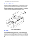
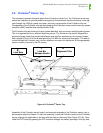
2.5 Front Panel Board
The FPC board provides power and monitors the tachometer readings from each individual fan
within the fan bay. The FPC also serves as a platform for the server controller switches, and sup-
ports circuitry required for server management.
The FPC board is located on the same plane as, and connects to the Profusion carrier board via
a connector. Both the FPC and Profusion carrier board are mounted to the topside of the Profu-
sion carrier tray. On the left front edge of the FPC board are three push button switches—power,
reset, and NMI. Each switch plunger has a small black cap on its end, which is necessary for the
proper operation of the buttons on the front bezel.
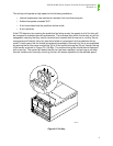
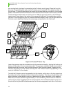
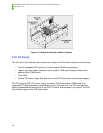
To install an FPC board, tilt the board forward as shown in Figure 2-6: Front Panel Board Installa-
tion, and insert the switches into the openings on the front flange of the Profusion carrier tray.
Lower the back of the board onto the standoffs on the tray. Align the board-to-board connectors
and slide the board back to engage the connectors. Secure with nine screws. Reverse this oper-
ation to remove the board.