OCPRF100 MP Server System Technical Product Specification
Revision 1.0
129
To switch between the SMC and FPC connection of COM2, both signals should be deasserted
before either signal is asserted.
When main power is off, the COM2_TO_SIO_EN signal should never be asserted.
10.2.10.7 Transmit and SMC/Front Panel Connection Control
The FPC’s interrupt 2 input is logically the same signal as the signal connected to the FPC’s RXD
pin. The description in this section, therefore, applies to both signals.
The FPC’s TXD pin drives both the COM2’s SOUT_TTL_COM2 signal and the ICMB’s
SOUT_TTL_ICMB signal.
10.2.10.8 COM2 Data Carrier Detect (DCD) Input Signal
COM2's data carrier detect (DCD) input is availabe as signal name DCD_TTL_FP. This input is
available to the firmware at all times, regardless of the states of any ICMB and COM2 control sig-
nals. This signal is a direct pass through from the COM2 port. The memory map location is
described in Section Memory Maps Memory Maps.
10.2.11 Front Panel Push Buttons
The OCPRF100 front panel has three momentary-contact push button switches: power, reset,
and NMI. The power and reset switches are easily accessible by the user, whereas the NMI but-
ton is accessible only via a “pinhole” protective cover. The power switch controls main system
power. If the system is powered off, pressing this button will always turn system power on. How-
ever, if the system is on, the microcontroller qualifies this button press with the current security
state of the system, and decides whether the system is actually to be powered off.
The power switch is available to the FPC and is described in Section Front Panel Power Switch.
The reset switch is available to the FPC and is described in Section Resetting the FPC.
10.2.11.1 Switch Debounce
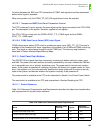
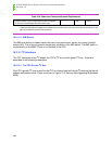
Table 10-8: Debounce Characteristics and Requirements describes the debounce characteristics
and requirements for all push button switches.
Table 10-8: Debounce Characteristics and Requirements
Event
Mininum (milli-
seconds) Typical
Maximum
(milliseconds)
Switch Press Ramp (High-Low) 0 20 200
Switch Release Ramp (Low-High) 0 12 150
Required switch cycle duration detection by firmware 50† 20 Infinity


