


OCPRF100 MP Server System Technical Product Specification
Revision 1.0
29
Notes: 1. There is no 240 VA protection circuit in the OCPRF100 MP server system.
2. Minimum load for second memory carrier is zero; assumes no carrier is installed.
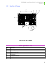
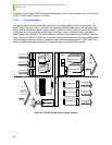
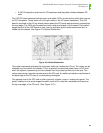
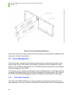
3.3.2 Cooling System
3.3.2.1 Description
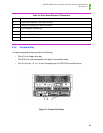
There are two independent cooling subsystems:
The upper system, encompassing the front panel, Profusion carrier, and I/O carrier.
The lower systems, encompassing the memory carriers, peripheral bay, and power supplies.
Air flows in through the bezel and exhausts out the rear of the chassis.
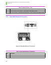
Cooling system redundancy to the upper system is provided by the 5+1 redundant fans at the
front top of the system. All systems come with redundant cooling for the upper area in standard
factory configuration with six upper system fans. Each fan provides tachometer signal output to
the front panel to indicate a fan failure. There may be time limit restrictions on the service time for
fan and PCI hot-plug card replacement.
Cooling system redundancy of the lower system is provided by the 2+1 system power supplies.
Each power supply fan provides tachometer signal output. A power supply fan failure is indicated
at the front panel as a predictive power supply failure. There may be time restrictions on the ser-
vice time for power supply hot swap replacement.
3.3.2.2 Redundancy and Ambient Temperature Control
3.3.2.2.1 System Fans
The front panel provides either of two fan input voltages to the system fans. Under normal ambi-
ent room conditions (less than 30°C), the front panel supplies 8.4 Vdc to the system fans. When
a system fan fails or when the room ambient temperature exceeds 30°C, the fan input voltage is
increased to 12 Vdc. Following a room temperature excursion above 30°C, the fan voltage does
not change back to 8.4 Vdc until the room temperature drops below 28°C and all system fans are
operational.
3.3.2.2.2 Power Supply Fans
The power supply fans are controlled independently by each supply. The ambient temperature
sensed at the inlet to each supply is used as the input to a control circuit, which continuously var-
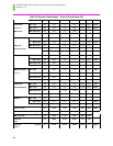
Total power (includes 2% distribution loss) 1268.1
9
Table 3-6: System Power Budget – Current (A) and Power (W)