


OCPRF100 MP Server System Technical Product Specification
Revision 1.0
13
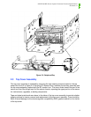
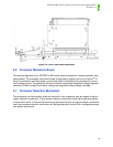
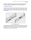
nectors begin to engage, rotate the levers back until the connectors are fully engaged. Levers
should be in an upright or near upright position. Secure the tray and the processor retention
mechanism to the sides of the chassis with screws (1) and (2) as indicated in Figure 2-9.
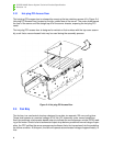
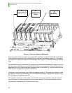
2.9 Midplane Assembly
The midplane assembly serves as an interconnect between the power supplies, memory boards,
Profusion carrier, and the I/O carrier. With the exception of limited server management and field
replaceable unit (FRU) components, the midplane assembly serves merely as an interconnection
device, routing the signals between the boards, while maintaining the signal integrity required for
the 100-MHz buses.
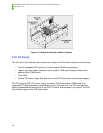
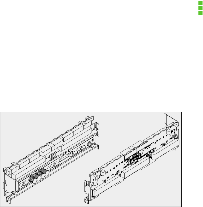
Figure 2-10: Midplane Assembly
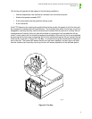
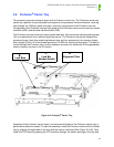
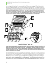
The midplane assembly is installed into the OCPRF100 MP server system chassis by rotating the
assembly about two alignment structures. The assembly is secured by a total of four screws, two
screws are located on each side of the system. All four screws must be removed to extract the
midplane assembly. The tab on the midplane assembly is used to manage the cables between
the I/O baseboard and the peripheral blind-mate board.