


OCPRF100 MP Server System Technical Product Specification
Revision 1.0
126
10.2.7.6 Development and Test Reset
In development and board testing the PLD and microcontroller can be put into a reset state by
asserting the PB_RST_L signal.
10.2.8 Speaker
The front panel contains a speaker that is controlled by either the FPC or the I/O board. The
speaker is energized if either source commands the speaker on. The speaker impedance is
approximately 8 ohms.
The FPC commands the speaker on by setting the PLD’s SPEAKER_LATCH. This latch also can
be read. The state of the I/O board’s speaker command cannot be read by the FPC.
During reset the SPEAKER_LATCH is set to deasserted (off, low).
10.2.9 Fan Control
There are six fans which plug into the front panel board. Each fan is powered from the VCCFAN
supply (see Section Dual Speed Fan Power, Dual Speed Fan Power). Each fan also has a
tachometer out signal, which is fed into Input Latch #1, to be monitored by the FPC. If a fan is
determined to have failed, the FAN_FAILED_L signal turns on the yellow fan failed LED on the
front panel. Also, an LED near the fan that has failed is illuminated by the FPC (via Output Latch
#1).
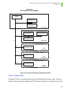
10.2.10 ICMB and COM2 Redirection
The ICMB/COM2 redirection circuitry provides a number of capabilities. These capabilities are
dealt with individually in the following subsections.
10.2.10.1 Receive Auto Switching
Both the COM2 RXD (received) and the ICMB RXD signals are routed to the front panel and are
continuously available, regardless of the state of any other control signals. In certain conditions it
is desirable to monitor both signals and to switch to whichever signal goes active first into the
FPC’s RXD input. This section covers such an auto-switch capability, implemented in the PLD.
The FP PLD supports auto-switching of the first-active incoming RXD signal into the incoming
RXD signals. The auto-switch is enabled by deasserting both the FORCE_RXD_ICMB_LATCH
and the FORCE_RXD_COM2_LATCH. When these are both deasserted by firmware, the PLD
goes into auto-switch mode.
Upon RXD activity, the microcontroller can determine which RXD signal is routed to the micro-
controller by reading the states of both FORCE bits within the PLD. Only the FORCE bit corre-
sponding to the switched RXD (ICMB or COM2) signal becomes asserted. In no case will both
FORCE bits become asserted.