OCPRF100 MP Server System Technical Product Specification
Revision 1.0
12
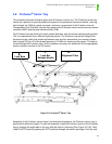
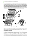
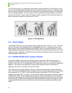
then moving back into place for connection to the Profusion carrier board. Place the four lock
bars over the protruding tabs and onto the Profusion carrier board (B). The release handles of
the lock bars (C) should be pointed to the outside of the board and they should be in the unlocked
position. Place the first mezzanine board on the left side of the Profusion carrier board, oriented
so the mezzanine board does not extend over the 1008-pin grand connector on the Profusion
carrier board. Press down in the center of the mezzanine board until it is seated down onto the
lock bars. If the configuration calls for a second mezzanine board, install it on the right side of the
Profusion carrier board by following the same steps as described for the first board.
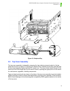
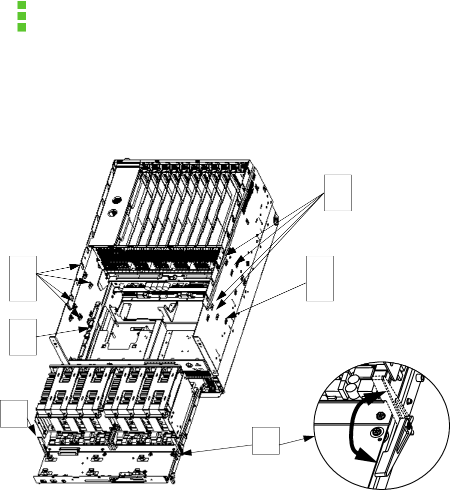
Figure 2-9: Profusion
®
Carrier Tray
Lower the processor retention mechanism onto the mezzanine board(s), aligning the hooks on its
bottom with the slots in the mezzanine board(s). The processor retention mechanism should be
oriented such that the center notch for the coherency filters is facing forward. Engage the four
lock bars by pushing in on their ends until they click. The Profusion carrier tray assembly is now
ready for installation in the chassis.
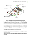
To install the Profusion carrier tray assembly into the chassis, set the tray on the tray supports on
the inside walls of the chassis and slide it towared the midplane. The tray and chassis have self-
aligning features to help guide the tray as it approaches the grand connector on the midplane.
When the connectors are within approximateily 1” from connecting, check under the Profusion
carrier tray for proper engagement of the center supports. The insertion/extraction levers (3) on
the side of the tray should be tilted forward as the connectors approach each other. As the con-
2
1
1
2
3
3


