OCPRF100 MP Server System Technical Product Specification
Revision 1.0
56
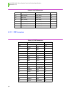
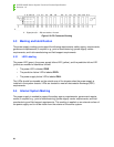
Notes: 1. Power blades (P1 – P12) are rated at 25 A each.
2. Signal pins (A1 – D6) are rated at 1 A each.
Figure 5-2: DC Connector Drawing
5.3 Marking and Identification
The power supply marking must support the following requirements: safety agency requirements,
government requirements (if required, e.g., point of manufacturing), power supply vendor
requirements, and Intel manufacturing and field support requirements.
5.3.1 LED Labeling
The power LED (green), the power supply failure LED (yellow), and the predictive failure LED
(yellow) are marked or labeled as follows.
• The power LED is labeled PWR.
• The predictive failure LED is labeled PRFL.
• The power supply failure LED is labeled FAIL.
The LEDs should be viewable on the outside rear of the chassis when the power supply is
installed in the system chassis.
LEDs are located to meet all electrostatic discharge (ESD)
requirements.
5.4 Internal System Marking
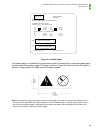
The power supply is marked to support the safety agency requirements, government require-
ments (if required, e.g., point of manufacturing), power supply vendor requirements, and Intel
manufacturing and field support requirements.
This marking is applied on an external surface of
the power supply and is not be visible from the exterior of the server system.


