


OCPRF100 MP Server System Technical Product Specification
Revision 1.0
33
• A 240 VA protective shield on the I/O baseboard and the plastic dividers between PCI
slots
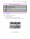
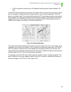
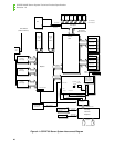
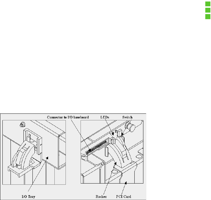
The LED PC board contains both the green and amber LEDs, as well as the switch that controls
the PCI slot power. These items will no longer reside on the I/O carrier baseboard. This LED
board is mounted in the I/O tray directly above where the PCI cards were previously screwed into
the tray ledge. The LEDs can be seen from both inside and outside of the chassis. Each switch
hangs down off of the LED board so that it can be activated by the rocker mechanism as it is
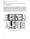
folded into the chassis. See Figure 3-9: Rocker Mechanism.
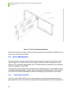
Figure 3-9: Rocker Mechanism
The rocker mechanism activates the slot power switch as it enters the I/O tray. The rocker can be
released only from within the chassis. This is to prevent unintentional power down of PCI slots
when the system is powered up and the chassis has not yet been pulled out of the rack. The
rocker also acts as a retention mechanism for the PCI card. An additional retention mechanism at
the back edge of the PCI card is currently being developed.
The opposite end of the PCI card is held in place by a plastic, snap-in, locking card guide. The
guide, installed on the center support bracket, has a built in retention mechanism that secures
the top-rear edge of the PCI card. (See Figure 3-10.)