


OCPRF100 MP Server System Technical Product Specification
Revision 1.0
123
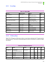
10.2.5 Front Panel LCD
The front panel LCD is a Stanley GMD1620A*. The LCD and the LCD’s LED backlighting unit are
powered off of the main +5 V. Therefore, this capability is only available when the +5 V power is
available.
In order to avoid loss of 5 V standby power and LCD latch-up, the firmware must comply with the
following. When main power is OFF, all signals driving the LCD should be disabled or driven low.
These include the D0 through D3, RW, EN, and RS signals. Also, when main power is removed
the LCD signals should be brought to this safe state within 200 µs.
10.2.6 System Power
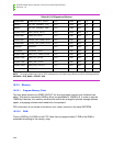
10.2.6.1 Power Supply Monitoring
Each of the three supplies has three signals that can be monitored. These are the PS_PRES,
PS_FAULT and the PRED_FAIL signals. These are available via the private I
2
C bus.
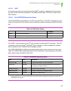
10.2.6.2 Power Interrupt Routing
There are three hardware signals that can initiate power cycling. They are the real time clock
(RTC) (PWR_CNTRL_RTC_L), the Intel
®
SMM card (PWR_CNTRL_SFC_L), and main power
going out (PWR_GOOD). These are accessed via the PWR_RTC_TRANS_LATCH, the
PWR_SFC_LATCH, and the PWR_GOOD_LATCH signals per the memory map. Upon asser-
tion, each of these signals is individually latched in the programmable logic device (PLD). The
asserted state remains latched even if the signal becomes deasserted. The asserted state
remains latched until the latch is read by the microcontroller. When read by the microcontroller,
the latch becomes cleared.
The PWR_CNTRL_RTC_L transition latch (PWR_RTC_TRANS_LATCH) becomes set
(asserted) on either transition of the PWR_CNTRL_RTC_L signal. When set, the latch remains
set until read by the FPC. Note that by reading the PWR_RTC_TRANS_LATCH latch, it is not
possible to obtain the absolute state of the PWR_CNTRL_RTC_L signal. Therefore, the
PWR_CNTRL_RTC_L signal can also be read by the FPC.
The PWR_CNTRL_SFC_L latch (PWR_SFC_LATCH) becomes set (asserted) on a high to low
transition of the PWR_CNTRL_SFC_L signal. When set, the latch remains set until read by the
FPC. When the latch is read, it becomes cleared and remains cleared until the next high to low
transition of the PWR_CNTRL_SFC_L signal. The state of the PWR_CNTRL_SFC_L signal can
also be read directly.
The PWR_GOOD_LATCH becomes set (asserted) when the PWR_GOOD signal has a high to
low transition. This occurs when main power goes bad. Once read, the latch is cleared and will
not be set until the next high to low transition. The state of the POWER_GOOD signal can also
be read directly. Each of these three latches is fed into a fourth latch (PWR_INTR_LATCH_L),
which drives the PWR_INTR_L signal. The PWR_INTR_L signal drives the FPC’s INT0 input.
This latch is asserted (low) if any of the power cycle signals become asserted (high). This latch
signal is deasserted (high) whenever it is read, as long as all three inputs are also deasserted.