


Register Descriptions Chapter 4
GPIB-1014 User Manual 4-62 © National Instruments Corporation
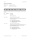
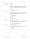
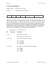
Interrupt Vector Registers
Each channel has a Normal Interrupt Vector Register (NIVR) and an Error Interrupt Vector
Register (EIVR), each consisting of eight bits. The CPU responds to an interrupt request from
the DMAC by executing an Interrupt Acknowledge Cycle. The GPIB-1014 hardware detects this
cycle and checks to see if the indicated priority matches its own programmable priority level (for
the VMEbus this can be level 1 through 7). If it does, the GPIB-1014 hardware acknowledges
the interrupt service to the DMAC and the DMAC completes the cycle by placing the appropriate
programmable interrupt vector on the lower eight bits of the data bus for the channel requesting
an interrupt.
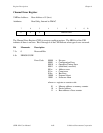
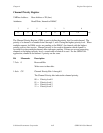
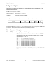
The EINT bit of the Channel Control Register (CCR) determines if an interrupt can be generated
by the channel. The interrupt request is generated if EINT is set and any of the three following
conditions is met:
• The COC bit is set in the CSR.
• The BTC bit is set in the CSR.
• The PCT bit is set and the PCL line is programmed to be an interrupt input.
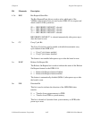
For GPIB DMA transfers, only channel 1 is used for interrupts. This is described in more detail
in Chapter 5.
The interrupt vector returned to the CPU comes from either the NIVR or the EIVR for the
channel. The NIVR is used unless the ERR bit of the CSR is set, in which case the error
interrupt vector is used. All interrupt vector registers in the DMAC are initialized to 0x0F on
power-up or reset.