


Chapter 4 Register Bit Descriptions
© National Instruments Corporation 4-3 GPIB-1014 User Manual
Register Description Format
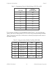
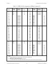
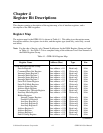
The remainder of this chapter discusses each of the GPIB-1014 registers in the order shown in
Table 4-1. Each register group is introduced, followed by a detailed bit description of each
register.
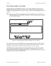
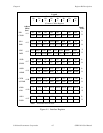
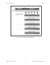
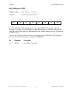
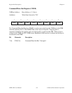
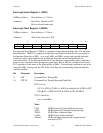
The register bit map shows a diagram of the register with the most significant bit (bit 15 for a
16-bit register, bit 7 for an 8-bit register) shown on the left, and the least significant bit (bit 0)
shown on the right. A square is used to represent each bit. Each bit is labeled with a name inside
its square. An asterisk (*) after the bit name indicates that the signal is active low. An asterisk is
equivalent to an overbar.
In many of the registers, several bits are labeled with an X, indicating don't care bits. When a
register is read, these bits may appear set or cleared, and should be ignored. If the register is
written to, these bit locations should be cleared.
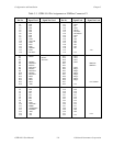
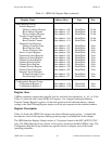
Mnemonics are assigned to messages, states, registers and bits. Most mnemonics contain a clue
to their meaning. Table 4-2 contains a list of clues to look for.
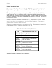
Table 4-2. Clues to Understanding Mnemonics
Clue Mnemonic Probably Stands For:
Ends in IE Interrupt Enable bit
Ends in EN Enable bit
4 letters, Interface function as defined in the
ends in S IEEE 488 standard
Ends in R,
R0, R1, R2 GPIB Program Register
3 letters,
uppercase Remote GPIB message
3 letters,
lowercase Local GPIB message
Appendix F contains an alphabetical list of mnemonics.