


Chapter 6 Theory of Operation
© National Instruments Corporation 6-23 GPIB-1014 User Manual
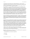
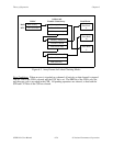
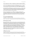
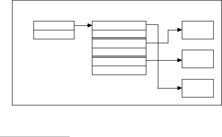
Start of array
# of entries = 3
BAR
BTC
DMAC
Memory Address A
Transfer Count A
Memory Address B
Transfer Count B
Memory Address C
Transfer Count C
Data Block
A
Data Block
B
Data Block
C
Address and
Transfer Count Array
Data Blocks
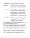
Figure 6-2. Array Format for Array Chaining Modes
Linked Chaining Operations. This type of chaining is very similar to array chaining. The
difference is that it uses a list in memory consisting of memory address, transfer counts, and
linked addresses. While array chaining requires a continuous address & transfer count array, the
linked address in each entry allows a non-continuous address & transfer count array. Each entry
in the chain list is 10 bytes long (four bytes to hold the address of the data block, two bytes to
hold the transfer count, and the last four bytes to hold the linked address of the next array entry.
The link address of the last array entry must be set to zero. Similar to array chaining, the BAR
points to the first array entry, but the BTCR is unused. Before starting any block transfers, the
DMAC fetches the entry currently pointed to by the BAR. The address information is placed in
the MAR, the count information is placed in the MTCR, and the link address replaces the current
contents of the BAR. The channel then begins a new block transfer. As each chaining entry is
fetched, the updated BAR is examined for the terminal link, which has all 32 bits equal to zero.
When the new base address is the terminal address, the chain is exhausted and the entry just
fetched determines the last block of the channel operation.
Linked chaining allows entries to be easily removed or inserted without having to reorganize data
within the chain. Since the end of the chain is indicated by a terminal link, the number of entries
in the chain need not be specified. The last four bytes in each entry (the link address) must be
even or the entry fetch results in an address error. The middle two bytes (the transfer count of
the data block) must be non-zero. The first four bytes in each entry (the starting address of the
data block) can be even or odd. Altogether, the address of first array entry must be even. If a
terminal count is loaded into the memory transfer counter, the count error is signaled.
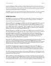
While it is not currently implemented in the GPIB-1014 software, the linked chaining method
could be used on Channel 0 to transfer large data blocks arbitrarily just like array chaining.
Similarly, you can use linked chaining on Channel 1 to implement the carry cycle feature, but
array chaining is much simpler. An example of the array format for linked chaining is shown in
Figure 6-3.