


Theory of Operation Chapter 6
GPIB-1014 User Manual 6-10 © National Instruments Corporation
If the carry cycle feature is not used in a DMA transfer, the CC bit in CFG1 is 0, and DMA
Gating and Control circuitry directs all DMA requests from the TLC to DMAC Channel 0.
DMAC Channel 1 is not used and must not be started.
Interrupter
The GPIB-1014 requests service by using the Interrupter circuitry. The circuitry consists of the
following:
• A 74145 open-collector 4-bit decoder
• Two 74F74 flip-flops
• A 74F85 4-bit magnitude comparator
• A 2-tap digital delay line
• Miscellaneous gates
The interrupt priority of the GPIB-1014 is software-selectable via three bits in CFG1. These bits
are connected to the 74145 and 74F85. Since all interrupts from the GPIB-1014 are routed
through the DMAC, the IREQ* pin of the DMAC is connected to the 74145. Seven of the 74145
outputs are connected directly to the seven VMEbus interrupt request lines IRQ1* through
IRQ7*. When the DMAC drives its IREQ* pin low, the VMEbus interrupt request line
corresponding to the interrupt priority code in CFG1 is driven low.
When the GPIB-1014 detects an interrupt acknowledge cycle (AS*, DS*, and IACK* all low),
the 74F85 compares VMEbus address lines A3 through A1 against the 3-bit interrupt priority
code in CFG1. If IACKIN* is asserted and the indicated priority does not match the GPIB-1014
priority, the daisy-chain signal IACKOUT* is asserted. This signal remains asserted until AS* is
released. However, if the priority indicated matches the GPIB-1014 priority, the IACK* pin of
the DMAC is driven low. The DMAC then finishes the acknowledge cycle by placing the
contents of Channel 1 NIVR (EIVR if a DMA error was encountered) on VMEbus data lines
D07 through D00 and driving the DTACK* line. An F74 flip-flop keeps the IACK* line of the
DMAC continuously asserted until the interrupt handler releases DS*. When IACK* is released,
the DMAC then releases the data transceiver and DTACK*. Notice the use of a 2-tap digital
delay line in the circuitry. The first delay is used to give the flip-flop enough data to clock setup
time and the second is used to prevent fluctuation in the flip-flop output from momentarily
asserting signals DIACK* or IACKOUT*.
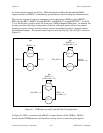
DTB Requester and Controller
The DTB Requester and Controller circuitry is designed to translate the bus request (BR*) from
the DMAC into the appropriate VMEbus arbitration protocol. This circuitry is responsible for
informing the DMAC that it has been granted the bus and for implementing the programmable
Release On Request feature. If the feature is enabled, the GPIB-1014 interface board, once
received and finished using the bus, simply holds control and releases the bus only when there