


Programming Considerations Chapter 5
GPIB-1014 User Manual 5-16 © National Instruments Corporation
i. For array or linked chaining, load the MFCR of Channel 1 with the proper value to
generate the desired address modifier code, which then accesses the data blocks. (See
Tables 3-1 and 3-2 for recommended values.)
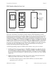
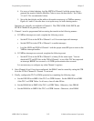
Note: If you are using the array chaining mode, construct a special carry cycle array in
memory. The array must begin at an even address and all addresses in the array
must be even. The contents of the array are as follows :
First four bytes = physical address of carry cycle byte
Next two bytes = 0001 (hex)
Next four bytes = physical address of last data byte in the data buffer to be
transferred
Last two bytes = 0002 (hex) (See Terminating the Transfer and Checking the
Result or Theory of Operation on why two bytes are required.)
j. For linked chaining mode, the carry cycle array is similar to the previous carry cycle
array, except that you need the link address to the next array entry. Figures 6-1 and 6-2
describe how to set up the array for both chaining modes.
The carry cycle byte is the command that is to be written to the AUXMR of the TLC
(send EOI, RFD Holdoff on ALL, and so on). This byte must be located somewhere in
memory where it can be accessed by the DMAC. The address of this byte is the first
element in the carry cycle array (four bytes). The DMAC uses this carry cycle array and
the chaining mode with Channel 1 to insert the TLC auxiliary command in the data
string. The MAR and MTCR are initialized and the carry cycle byte is transferred. The
MAR and MTCR are then reloaded and the last byte of the data buffer is transferred.
k. Program Channel 1 in the following manner before starting the transfer:
• If VMEbus interrupts are used:
(1) Set the PCL bits in the DCR of Channel 1 to 01 for status input with interrupt.
(2) Set the EINT bit in the CCR of Channel 1 to enable interrupts.
(3) Load the NIVR and EIVR of Channel 1 with the proper status/ID byte to return
to the VMEbus interrupt handler.
• If VMEbus interrupts are not used, set the PCL bits in the DCR of Channel 1 to 00 for
status input. You can check the PCT and PCS bits in the CSR of Channel 1 to see if
the TLC has interrupted, BERR* has occurred, or if GPIB handshake synchronization
has occurred.
It is not necessary to write to the MTCR, MAR, DAR, DFCR, or CPR of Channel 1.