


Chapter 5 Programming Considerations
© National Instruments Corporation 5-13 GPIB-1014 User Manual
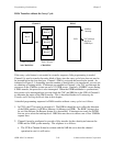
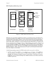
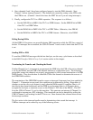
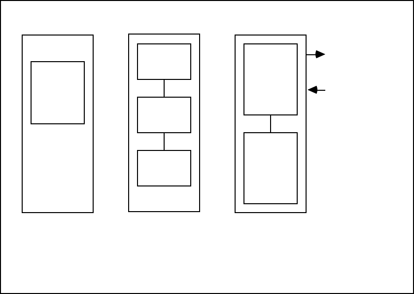
DMA Transfers with the Carry Cycle
Channel 0
Data
Block
A
Total=N-1 bytes
NO CHAINING
OR
Total=N-1 bytes
Data
Block A
Data
Bock B
Data
Block C
CHAINING
Channel 1
Block A
Count=1
Block B
Count=2
Carry Cycle byte
+ Nth data byte
CHAINING
(array or linked)
(array or linked)
(carry cycle
byte)
(last data
byte)
VMEbus
interrupt
TLC interrupt
Bus Error
GPIB Sync.
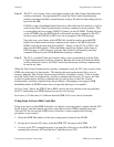
Figure 5-2. DMA Transfer with Carry Cycle
When the carry cycle feature is needed in a transfer, it is transparent to the system CPU and is
automatically handled by the GPIB-1014 once the channels have been properly configured. As
indicated earlier in this chapter, Channel 1 is now used to transfer the carry cycle byte and the
last data byte. Setting up Channel 0 is similar to the steps used to program the DMA explained
earlier in this chapter. Channel 1 is set up to transfer two tiny blocks of data. It is easiest to use
the array chaining mode on Channel 1; however, linked chaining is also possible. Channel 1 can
also be configured to generate VMEbus interrupts. When the GPIB is finally synchronized, you
can check the COC and ERR bit in the CSR of Channel 0 to determine the status of the DMA
transfer of the first n-1 bytes. The success of the DMA transfer is determined by examining the
MTCR of Channel 1. Refer to the Terminating the Transfer and Checking the Result section
later in this chapter for more details.
A detailed programming sequence for DMA transfers with a carry cycle is as follows:
1. In CFG1, set the CC bit in CFG1 to a 1 to enable the carry cycle feature. Set the DIR bit to
reflect the direction of the DMA transfer (1=GPIB-to-Memory, 0=Memory-to-GPIB). Set
the ROR* bit if the Release On Request feature is to be enabled. If interrupts are used, the
INTRQ bits are set to select the interrupt level. BRG bits must be set to choose one of four
VMEbus request lines.