


Chapter 3 Configuration and Installation
© National Instruments Corporation 3-5 GPIB-1014 User Manual
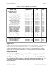
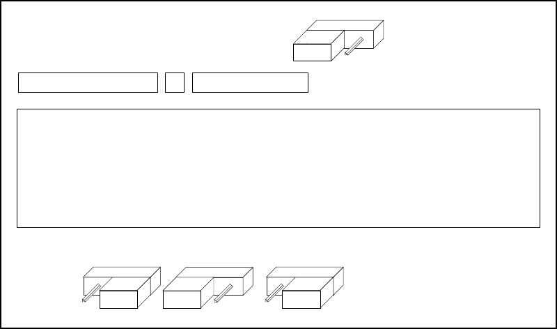
DMA Address Modifier Code Output
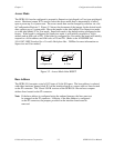
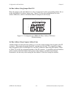
During a DMA cycle, the GPIB-1014 sends out a 6-bit Address Modifier (AM) code to the
VMEbus lines AM5 through AM0. The correct code is obtained by both programming the
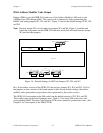
DMAC and setting jumpers W3, W4, and W5. Figure 3-4 shows the default settings of W3, W4,
and W5.
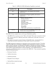
Note: Because jumper W5 is not located near jumpers W3 and W4, Figure 3-4 outlines and
labels the components on the GPIB-1014 interface board that are found between jumper
W5 and the other jumpers.
0110US
AM1' AM1
W5
U32 C33 U33
W4
W3
68450
F245 F322
W2
Figure 3-4. Default Settings of AM Code Jumpers W3, W4, and W5
Rev. D and earlier versions of the GPIB-1014 do not have jumpers W3, W4, and W5. If all of
the jumpers on later versions of the board remain in their factory default settings, the address
modifier codes generated are equivalent to those generated by the earlier versions.
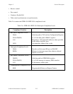
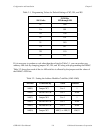
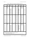
The GPIB-1014 can produce eight AM codes from the default settings of W3, W4, and W5.
These eight codes are the most commonly used. Table 3-1 lists these AM codes next to the
corresponding DMAC Function Code Register (FCR) values needed to produce the codes. (See
Chapter 4 for a description of the DMAC FCR.)