


Chapter 3 Configuration and Installation
© National Instruments Corporation 3-7 GPIB-1014 User Manual
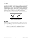
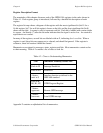
For example, to produce an AM code of 17 hex (a binary value of 010111), complete the
following steps:
1. Set jumper W3 to 0.
2. Set jumper W4 to 0.
3. Set jumper W5 to AM(1).
4. Write the pattern 00000111 to the FCR of the DMAC.
Other Configuration Parameters
All other configuration parameters for the GPIB-1014 are software-selectable, including the
following:
• Selecting one of seven interrupt request lines (IRQ1* through IRQ7*)
• Selecting one of four Bus Request lines (BR0* through BR3*)
• Enabling the Release On Request (ROR) feature
• Selecting the automatic carry cycle feature
• Enabling the GPIB-1014 to be the GPIB System Controller
• Selecting the color of front panel SYSFAIL LED indicator (Red/Green)
• Selecting the DMA transfer mode
Software control of these parameters gives you the flexibility to tailor operation and performance
to meet the specific requirements of separate tasks within your system.
Installation
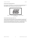
The GPIB-1014 is a dual-height board that interfaces to the VMEbus P1 and P2 connectors.
There are two options for the GPIB I/O from the GPIB-1014 interface board. The following
paragraphs describe the GPIB-1014 interface to the VMEbus backplane and to the IEEE 488 bus.
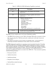
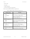
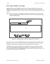
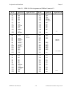
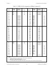
Verification of System Compatibility
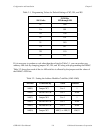
The GPIB-1014 does not use all of the signals included in the VMEbus specification. Compare
signals listed in Tables 3-3 and 3-4 to those signals used by the VMEbus system in which the
GPIB-1014 will be installed. This is to ensure that the two are compatible (that is, the
GPIB-1014 has all the necessary signals needed by the system and vice versa).
Note: For models GPIB-1014-1S and GPIB-1014-1S-EH, there are no signals connected to the
P2 connector except for power (+5 V) and ground signals.