


Chapter 4 Register Descriptions
© National Instruments Corporation 4-51 GPIB-1014 User Manual
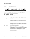
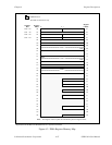
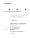
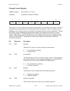
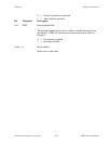
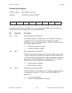
Device Control Register
VMEbus Address: Base Address + 04 (hex)
Attributes: Read/Write, Internal to DMAC
7 654 3210
XRM DTYP DPS 0 PCL R/W
The Device Control Register (DCR) is a device-soriented control register.
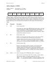
Bit Mnemonic Description
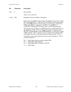
7-6r/w XRM External Request Mode Bits 7 through 6
The External Request Mode bits indicate whether the channel is in
cycle steal or cycle steal with hold transfer mode. These two modes
are used in all GPIB applications. Burst mode is not used in
GPIB-1014 GPIB data transfers, but may be used in
memory-to-memory transfers.
00 = Burst Transfer Mode
10 = Cycle Steal Mode
01 = Undefined, Reserved
11 = Cycle Steal with Hold Mode
5-4r/w DTYP Device Type Bits 5 through 4
The Device Type bits indicate what type of device is on the channel.
For the GPIB-1014 GPIB application, set the device type to 10 (device
with ACK). For memory-to-memory transfers, set the device type to
00 (68000-compatible).
00 = 68000-compatible, explicitly addressed
01 = 6800-compatible, explicitly addressed
10 = Device with ACK, implicitly addressed
11 = Device with ACK and READY
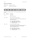
3r/w DPS Device Port Size Bit
The Device Port Size bit indicates the size of the device port. For
GPIB-1014 GPIB transfers, the device port size is 8 bits. For
memory-to-memory transfers, the device port size can be 8 or 16 bits.
0 = 8-bit port
1 = 16-bit port