


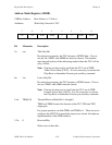
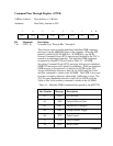
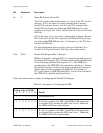

Table 4-5 shows the functions that are executed when the AUXMR Control Code (CNT2
through CNT0) is loaded with 000 (binary) and the Command Code (COM4 through COM0) is
loaded.
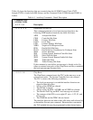
Table 4-5. Auxiliary Commands: Detail Description
Command Code
(COM4-COM0)
4 3 2 1 0 Description
0 0 0 0 0 Immediate Execute Pon
This command generates a local pon message that places the
following GPIB interface functions into these idle states:
AIDS Acceptor Idle State
CIDS Controller Idle State
LIDS Listener Idle State
LOCS Local State
LPIS Listener Primary Idle State
NPRS Negative Poll Response State
PPIS Parallel Poll Idle State
PUCS Parallel Poll to Unaddressed to Configure State
SIDS Source Idle State
SIIS System Control Interface Clear Idle State
SPIS Serial Poll Idle State
SRIS System Control Remote Enable Idle State
TIDS Talker Idle State
TPIS Talker Primary Idle State
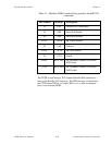
If the command is sent while a pon message is already active (by
either an external reset pulse or the Chip Reset auxiliary command)
the local pon message becomes false.
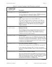
0 0 0 1 0 Chip Reset
The Chip Reset command resets the TLC in the same way as an
external reset pulse. The System Controller bit is also cleared.
The TLC is reset to the following conditions:
• The local pon message is set and the interface functions are
placed in their idle states.
• All bits of the SPMR are cleared.
• The EOI bit is cleared.
• All bits of the AUXRA, AUXRB, and AUXRE are cleared.
• The Parallel Poll Flag and RSC local message are cleared.
• The contents of the ICR is set to eight (F3 set to 1; F2, F1, and
F0 set to 0).
• The TRM0 bit and the TRM1 bit are cleared.
The interface functions are held in their idle states until released by
an Immediate Execute pon command. Between these commands,
the TLC unitable bits may be programmed to their desired states.
(continues)