


Programming Considerations Chapter 5
GPIB-1014 User Manual 5-2 © National Instruments Corporation
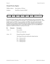
• The Transit Receive Mode 0 (TRM0) and Transit Receive Mode 1 (TRM1) bits in the
Address Mode Register (ADMR) are cleared.
All other TLC register contents should be considered as undefined while the LMR bit is set and
after LMR has been cleared. While the TLC internal signal pon is set, all Auxiliary Mode
Register (AUXMR) commands are cleared and cannot be executed. All other TLC registers can
be programmed while pon is set. When pon is released or cleared (by issuing an Immediate
Execute pon auxiliary command to the TLC), the interface functions are released from the pon
state and the auxiliary commands can be executed.
The 68450 DMAC is initialized as follows:
1. All bits of the General Control Register (GCR), Device Control Register (DCR), Operation
Control Register (OCR), Sequence Control Register (SCR), Channel Control Register
(CCR), Channel Status Register (CSR), Channel Priority Register (CPR), and Channel
Error Register (CER) are cleared for all channels. This resets the Start (STR), Continue
(CNT), Channel Active (ACT) and interrupt generation bits and clears the status and error
bits.
2. The interrupt vector registers (Normal Interrupt Vector Register (NIVR) and Error Interrupt
Vector Register (EIVR)) for all channels are set to 0x0F (hex).
A typical programmed initialization sequence for the GPIB-1014 might include the following
steps:
1. Set and then clear the Local Master Reset (LMR) bit in Configuration Register 2 (CFG2) to
place the GPIB-1014 in a known, quiescent state.
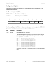
2. Load the two GPIB-1014 Configuration Registers (CFG1 and CFG2) with the appropriate
values to configure the desired operation.
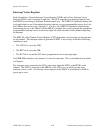
3. Set or clear the desired interrupt enable bits in Interrupt Mask Register 1 (IMR1) and
Interrupt Mask Register 2 (IMR2) of the TLC.
4. If a VMEbus interrupt is used, the PCL bits in Channel 1 DCR must be set to 01 for status
input with interrupt. In addition, bit EINT in Channel 1 CCR must be set for Channel 1 to
generate an interrupt. If polling (no interrupt) is used, set PCL bits to 00 for status input
without interrupts. Bit EINT should be cleared.
5. If the VMEbus interrupt is used, load the DMAC Channel 1 NIVR and EIVR with the
desired GPIB-1014 Status/ID byte.
6. Load the TLC primary GPIB address in Address Register 0 (ADR0) and Address Register
1 (ADR1).
7. Enable or disable the GPIB Talker and Listener functions and addressing mode using the
ADMR.
8. Load the Serial Poll response in the SPMR.