


Programming Considerations Chapter 5
GPIB-1014 User Manual 5-6 © National Instruments Corporation
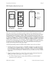
The GPIB-1014 as GPIB Talker and Listener
The TLC may be either GPIB Talker or Listener, but not both simultaneously. Either function is
deactivated automatically if the other is activated. The TA, LA, and ATN* bits in the ADSR
together indicate the specific state of the TLC.
ATN* TA LA
0 1 0 Addressed Talker–cannot send data
1 1 0 Active Talker–can send data
0 0 1 Addressed Listener–cannot receive data
1 0 1 Active Listener–can receive data
The Address Status Change (ADSC), Command Output (CO), Address Pass Through (APT),
Data Out (DO), and Data In (DI) status bits are used to prompt the program (possibly with an
interrupt request) when a change of state occurs.
The following sections discuss several aspects of data transfers.
Programmed Implementation of Talker and Listener
When there is no Controller in the GPIB system, the ton and lon address modes (refer to the
description of the ADMR) are used to activate the TLC GPIB Talker and Listener functions. If
used, ton or lon should be set during TLC initialization.
When the TLC is GPIB Active Controller, the Listen and Local Unlisten programmed auxiliary
commands are used to activate and deactivate the TLC GPIB Listener function.
Addressed Implementation of the Talker and Listener
The TLC, when GPIB Active Controller, can address itself by sending its own GPIB Talk or
Listen address using the CO bit and the CDOR. When another device on the GPIB is acting as
Controller, the TLC is addressed with GPIB command messages to become a Talker or Listener.
Address Mode 1
If the TLC ADMR has been configured for Address Mode 1, the TLC responds to the reception
of two primary GPIB addresses: major and minor. Upon receipt of its major or minor MTA or
its major or minor MLA from the GPIB Active Controller, the TLC is addressed as Talker or
Listener. If the TLC has received its GPIB Talk Address, the TA bit in the ADSR is set, the
ADSC bit in ISR2 is set, and the DO bit in ISR1 is set. If the TLC has received its GPIB Listen
address, the LA bit in the ADSR is set, the ADSC bit in ISR2 is set, and the DI bit in ISR1 is set
when the first GPIB data byte is received.