


Chapter 6 Theory of Operation
© National Instruments Corporation 6-27 GPIB-1014 User Manual
request is enabled for the condition. An important fact to remember is that ISR1 and ISR2 are
always cleared when read, even if the condition that caused the bit to be initially set remains true.
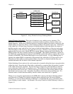
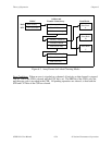
Data to and from the GPIB is pipelined through the CDOR and DIR respectively. An 8-MHz
clock is used as the CLOCK input to the TLC. For proper GPIB timing, the internal counter
must be programmed to eight. The TLC RESET pin is driven by the GPIB-1014 RESET signal.
Connecting the TLC to the GPIB itself are two multi-function transceivers, one handling the data
lines (a 75160A) and the other handling the handshake and management lines (a 75162A). The
75160A and 75162A transceivers are specifically designed to meet the IEEE 488 driver and
receiver specifications. In particular, they do not affect bus operations when the GPIB-1014
power is removed or during power up or down transitions.
The TLC controls the direction of the 16 GPIB signals, depending on whether the chip is
functioning as a GPIB Talker, Listener, or Controller. The SC bit of CFG2, when set to a logic
one, programs the 75162 transceiver to drive or receive the GPIB IFC* and REN* control lines.
The data lines are always driven in the 3-state mode unless the TLC receives a parallel poll
message (ATN and EOI both true), at which time the drivers are switched to Open Collector
mode.
Test and Troubleshooting
The GPIB-1014 is designed to aid acceptance testing and troubleshooting of either hardware
failures or software bugs. The hardware provides several features that enable stand-alone testing.
DMA Stand-Alone Testing
Most of the GPIB-1014 ICs and interconnecting circuitry are associated with implementing the
DMA function. From the system's point of view, the best acceptance test for the interface is one
in which DMA data is transferred between the VMEbus memory and a GPIB device. Should
there be problems associated with implementing this type of test, a good troubleshooting tactic is
to start removing variables in the system, starting with the DMAC itself. The GPIB-1014 is
designed to perform DMA transfers without needing an external GPIB device. This can be
implemented using the flowthrough mode of the DMAC to perform memory-to-memory DMA
transfers. This feature allows test and verification of the DMAC, the DTB Requester, the
Interrupter, and the VMEbus interface. Any of the DMAC channels can be configured to
transfer a buffer of data from one location in memory to another, and the new buffer can be
compared against expected results. The DMAC must be configured to provide flowthrough
transfers using the automatic request mode.
GPIB Interface Testing
The NDAC* and DIO1* bits can be used to determine if the output signals of the TLC, the
75160A, and the 75162A are functioning properly. Since most failures (including problems with
shorts or open on the printed wire board) prevent the TLC from working at all, this test gives