


© National Instruments Corporation 2-1 GPIB-1014 User Manual
Chapter 2
General Description
This chapter contains the electrical specifications for the GPIB-1014, the data transfer features,
and describes the characteristics of key interface board components.
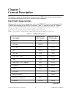
Electrical Characteristics
All integrated circuit drivers and receivers used on the GPIB-1014 meet the requirements of the
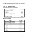
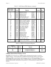
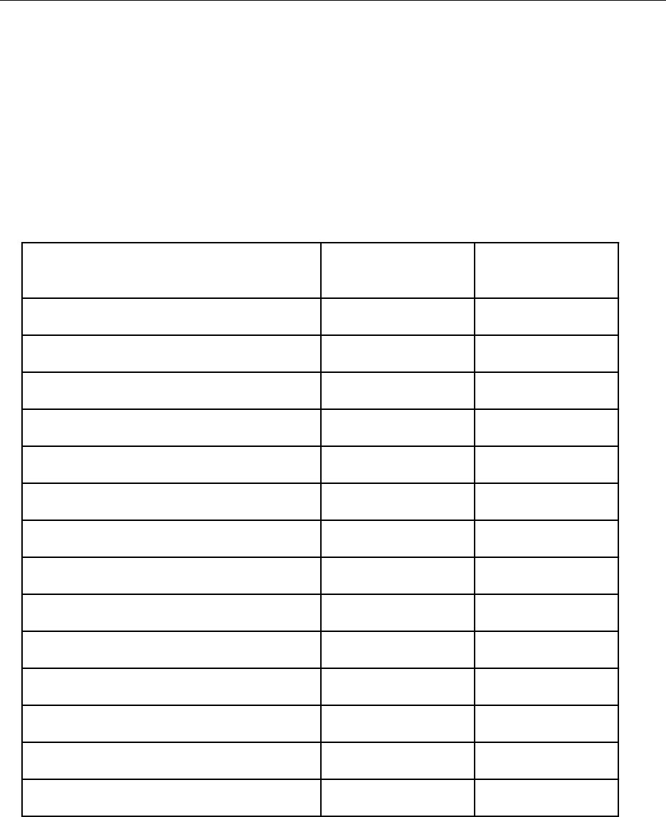
VMEbus specification and the IEEE 1014 standard. Table 2-1 contains a list of the VMEbus
signals used by the GPIB-1014 and the electrical loading presented by the circuitry on the
interface board (in terms of device types and their part numbers).
Note: The asterisk (*) after the bus signal indicates that the signal is active low.
Table 2-1. GPIB-1014 Signals
Driver Device Receiver Device
Bus Signals Part Number Part Number
D00-D15 F245 F245
A23-A16 AS573 –
A15-A09 AS573 LS2521
A8 AS573 F1241
A07-A01 F245 F245
AM5-AM3, AM0 F241 LS2521
AM2 F241 LS240
DS0*, DS1*, AS*, WRITE* F241 F1241
LWORD* F241 LS2521
IACK* F241 F1241
SYSCLK – LS240
BG0IN*-BG3IN* – LS241
BG0OUT*-BG3OUT* F241 –
DTACK* AS756 LS240
(continues)