


Chapter 3 Configuration and Installation
© National Instruments Corporation 3-3 GPIB-1014 User Manual
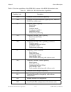
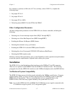
Access Mode
The GPIB-1014 can be configured to respond to Supervisor (privileged) or User (non-privileged)
access. Hardware jumper W2 is used to select the access mode that is automatically in effect
upon a power-up or a system reset. The access mode then can be changed by software via a bit
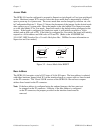
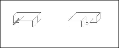
in Configuration Register 2. Figure 3-2 shows the placement of the jumper for the desired mode
after a power-up or a system reset. Move the jumper to the side labeled S for Supervisor mode,
or to the side labeled U for User mode. Supervisor mode is the default setting configured at the
factory. If the board is configured for Supervisor mode, it will initially respond to a 16-bit
address and an AM code of 2D. If the board is configured for User mode, the board will initially
respond to a 16-bit address and AM codes of 29 and 2D. (Refer to the ANSI/IEEE Std.
1014-1987, IEEE Standard for a Versatile Backplane Bus: VMEbus for more information on
Supervisor and User modes.)
a. Supervisor b. User
W2
US
W2
US
Figure 3-2. Access Mode After RESET
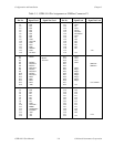
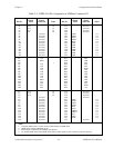
Base Address
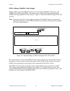
The GPIB-1014 occupies a total of 512 bytes of 16-bit I/O space. The base address is selected
with either hardware jumper block W1 on the interface board or compare address lines located
on the P2 connector. The 1S and 1S-EH versions of the GPIB-1014 do not have compare
address lines located on the P2 connector.
Note: If the base address is configured using the onboard jumpers, the lines must not
be strapped on the P2 connector. Likewise, if the base address is configured
on the P2 connector, the jumpers provided on the interface board must be
removed.