


Appendix A Specifications for AT-MIO-16E-1, AT-MIO-16E-2 and AT-MIO-64E-3
AT-MIO/AI E Series User Manual A-2
National Instruments Corporation
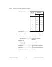
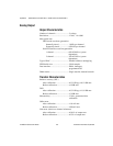
Input coupling....................................DC
Max working voltage
(signal + common mode).................Each input should remain within
±11 V of ground
Overvoltage protection.......................±25 V powered on, ± 15 V
powered off
Inputs protected.......................... ACH<0..63>, AISENSE,
AISENSE2
FIFO buffer size
AT-MIO-16E-1........................... 8,192 samples
AT-MIO-16E-2,
AT-MIO-64E-3........................... 2,048 samples
Data transfers.....................................DMA, interrupts, programmed
I/O
DMA modes.......................................Single transfer, demand transfer
Configuration memory size................512 words
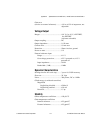
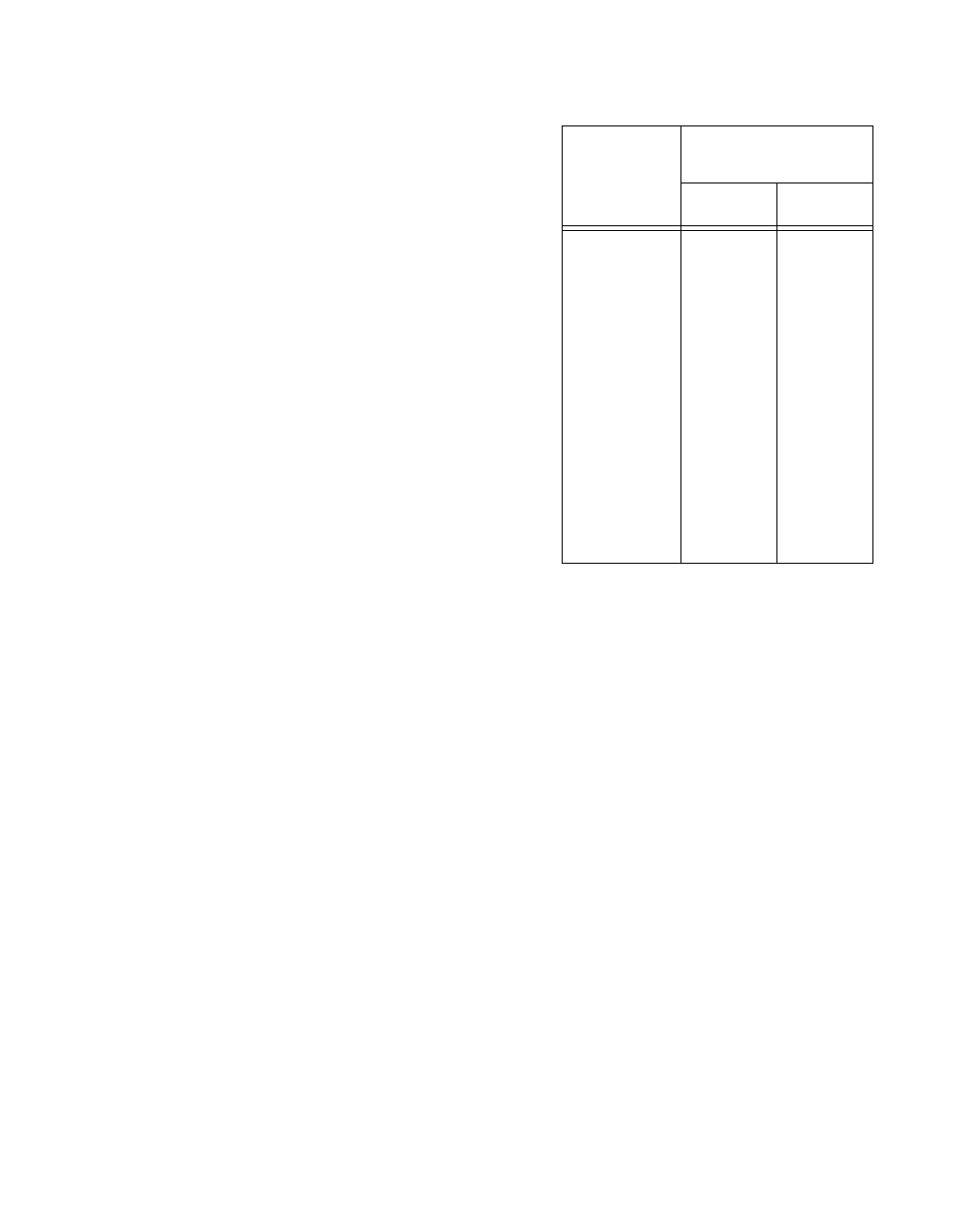
Input signal ranges.................
Board Gain
(Software
Selectable)
Board Range
(Software Selectable)
Bipolar Unipolar
0.5 ±10 V
—
1
±5 V
0 to 10 V
2
±2.5 V
0 to 5 V
5
±1 V
0 to 2 V
10
±500 mV
0 to 1 V
20
±250 mV
0 to 500 mV
50
±100 mV
0 to 200 mV
100
±50 mV
0 to 100 mV