


Chapter 4 Signal Connections
National Instruments Corporation 4-35 AT-MIO/AI E Series User Manual
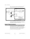
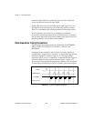
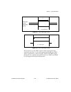
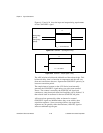
Figure 4-17. TRIG1 Input Signal Timing
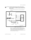
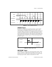
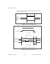
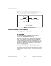
Figure 4-18. TRIG1 Output Signal Timing
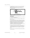
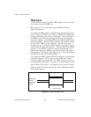
The board also uses the TRIG1 signal to initiate pretriggered data
acquisition operations. In most pretriggered applications, the TRIG1
signal is generated by a software trigger. Refer to the TRIG2 signal
description for a complete description of the use of TRIG1 and TRIG2
in a pretriggered data acquisition operation.
Rising-edge
polarity
Falling-edge
polarity
t
w
t
w
= 10 ns minimum
t
w
t
w
= 50-100 ns