


Chapter 4 Signal Connections
AT-MIO/AI E Series User Manual 4-44
National Instruments Corporation
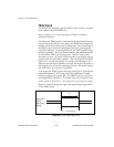
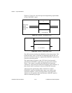
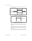
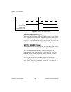
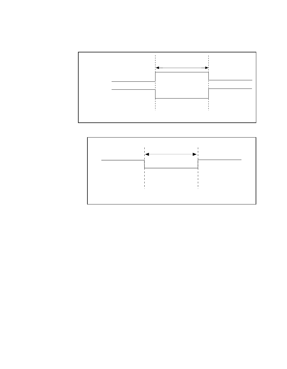
Figures 4-28 and 4-29
show the input and output timing requirements
for the UPDATE* signal.
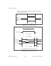
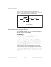
Figure 4-28. UPDATE* Input Signal Timing
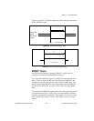
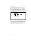
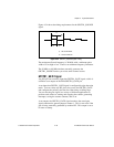
Figure 4-29. UPDATE* Output Signal Timing
The DACs are updated within 100 ns of the leading edge. Separate the
UPDATE* pulses with enough time that new data can be written to the
DAC latches.
The AT E Series board UI counter normally generates the UPDATE*
signal unless you select some external source. The UI counter is started
by the WFTRIG signal and can be stopped by software or the internal
Buffer Counter.
D/A conversions generated by either an internal or external UPDATE*
signal do not occur when gated by the software command register gate.
Rising-edge
polarity
Falling-edge
polarity
t
w
t
w
= 10 ns minimum
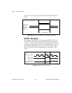
t
w
t
w
= 300-350 ns