


Chapter 4 Signal Connections
National Instruments Corporation 4-41 AT-MIO/AI E Series User Manual
AIGATE Signal
Any PFI pin can externally input the AIGATE signal, which is not
available as an output on the I/O connector. The AIGATE signal can
mask off scans in a data acquisition sequence. You can configure the
PFI pin you select as the source for the AIGATE signal in either the
level-detection or edge-detection mode. You can configure the polarity
selection for the PFI pin for either active high or active low.
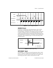
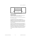
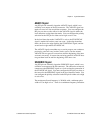
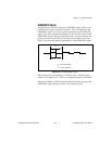
In the level-detection mode if AIGATE is active, the STARTSCAN
signal is masked off and no scans can occur. In the edge-detection
mode, the first active edge disables the STARTSCAN signal, and the
second active edge enables STARTSCAN.
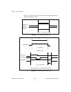
The AIGATE signal can neither stop a scan in progress nor continue a
previously gated-off scan; in other words, once a scan has started,
AIGATE does not gate off conversions until the beginning of the next
scan and, conversely, if conversions are being gated off, AIGATE does
not gate them back on until the beginning of the next scan.
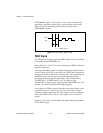
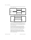
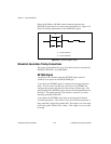
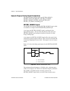
SISOURCE Signal
Any PFI pin can externally input the SISOURCE signal, which is not
available as an output on the I/O connector. The onboard scan interval
counter uses the SISOURCE signal as a clock to time the generation of
the STARTSCAN signal. You must configure the PFI pin you select as
the source for the SISOURCE signal in the level-detection mode. You
can configure the polarity selection for the PFI pin for either active high
or active low.
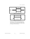
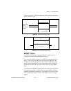
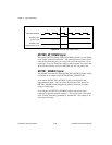
The maximum allowed frequency is 20 MHz, with a minimum pulse
width of 23 ns high or low. There is no minimum frequency limitation.