


Chapter 4 Signal Connections
National Instruments Corporation 4-17 AT-MIO/AI E Series User Manual
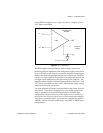
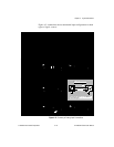
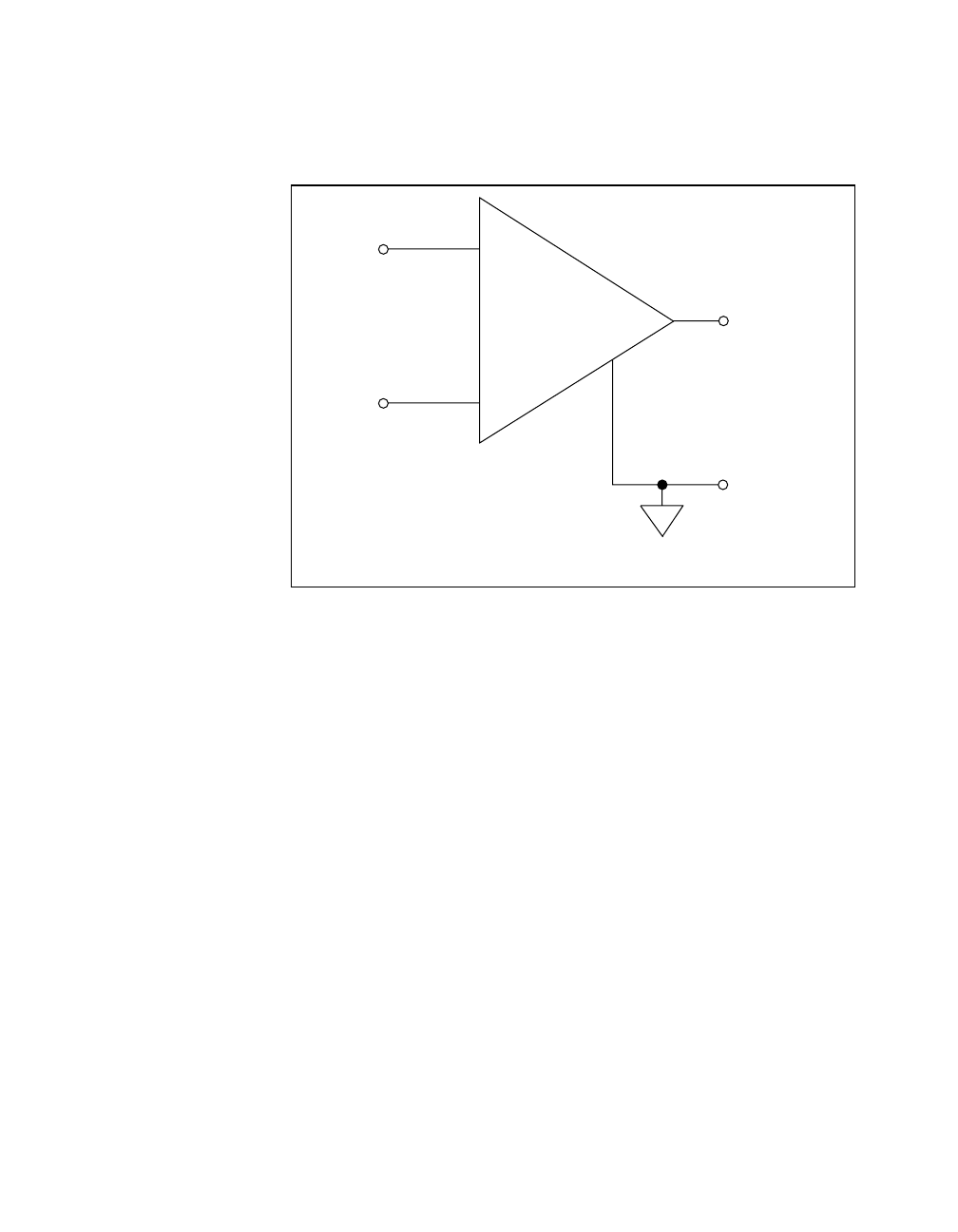
use the PGIA in different ways. Figure 4-4 shows a diagram of your
AT E Series board PGIA.
Figure 4-4. AT E Series PGIA
The PGIA applies gain and common-mode voltage rejection and
presents high input impedance to the analog input signals connected to
your AT E Series board. Signals are routed to the positive and negative
inputs of the PGIA through input multiplexers on the board. The PGIA
converts two input signals to a signal that is the difference between the
two input signals multiplied by the gain setting of the amplifier. The
amplifier output voltage is referenced to the ground for the board. Your
AT E Series board A/D converter (ADC) measures this output voltage
when it performs A/D conversions.
You must reference all signals to ground either at the source device or
at the board. If you have a floating source, you should reference the
signal to ground by using the RSE input mode or the DIFF input
configuration with bias resistors (see the Differential Connections for
Nonreferenced or Floating Signal Sources section later in this chapter).
If you have a grounded source, you should not reference the signal to
AIGND. You can avoid this reference by using DIFF or NRSE input
configurations.
-
Instrumentation
Amplifier
-
Measured
Voltage
V
m
+
+
PGIA
V
in+
V
in-
V
m
= [V
in+
- V
in-
]* Gain