


Chapter 1 Introduction
AT-MIO/AI E Series User Manual 1-6
National Instruments Corporation
Custom Cabling
National Instruments offers cables and accessories for you to prototype
your application or to use if you frequently change board
interconnections.
If you want to develop your own cable, however, the following
guidelines may be useful:
• For the analog input signals, shielded twisted-pair wires for each
analog input pair yield the best results, assuming that you use
differential inputs. Tie the shield for each signal pair to the ground
reference at the source.
• You should route the analog lines separately from the digital lines.
• When using a cable shield, use separate shields for the analog and
digital halves of the cable. Failure to do so results in noise coupling
into the analog signals from transient digital signals.
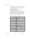
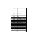
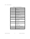
The following list gives recommended part numbers for connectors that
mate to the I/O connector on your AT E Series board.
Mating connectors and a backshell kit for making custom 68-pin
cables are available from National Instruments (part number
776832-01)
♦ AT-MIO-16E-1, AT-MIO-16E-2, AT-MIO-16E-10,
AT-MIO-16XE-10, AT-AI-16XE-10, and the AT-MIO-16XE-50
Honda 68-position, solder cup, female connector (part number
PCS-E68FS)
Honda backshell (part number PCS-E68LKPA)
♦ AT-MIO-64E-3 and AT-MIO-16DE-10
AMP 100-position IDC male connector (part number 1-750913-9)
AMP backshell, .50 max O.D. cable (part number 749081-1)
AMP backshell, .55 max O.D. cable, (part number 749854-1)