


Chapter 4 Signal Connections
AT-MIO/AI E Series User Manual 4-48
National Instruments Corporation
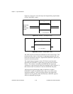
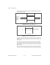
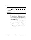
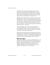
Figure 4-33. GPCTR0_OUT Signal Timing
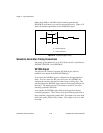
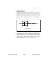
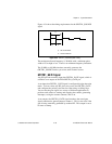
GPCTR0_UP_DOWN Signal
This signal can be externally input on the DIO6 pin and is not available
as an output on the I/O connector. The general-purpose counter 0 will
count down when this pin is at a logic low and count up when it is at a
logic high. You can disable this input so that software can control the
up-down functionality and leave the DIO6 pin free for general use.
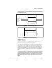
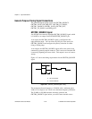
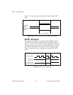
GPCTR1_SOURCE Signal
Any PFI pin can externally input the GPCTR1_SOURCE signal, which
is available as an output on the PFI3/GPCTR1_SOURCE pin.
As an input, the GPCTR1_SOURCE signal is configured in the
edge-detection mode. You can select any PFI pin as the source for
GPCTR1_SOURCE and configure the polarity selection for either
rising or falling edge.
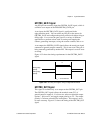
As an output, the GPCTR1_SOURCE monitors the actual clock
connected to general-purpose counter 1. This is true even if the source
clock is being externally generated by another PFI. This output is set
to tri-state at startup.
GPCTR0_SOURCE
GPCTR0_OUT
GPCTR0_OUT
(Toggle output on TC)
(Pulse on TC)
TC