


Chapter 3 Hardware Overview
National Instruments Corporation 3-19 AT-MIO/AI E Series User Manual
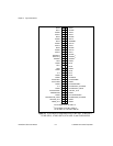
Digital I/O
The AT E Series boards contain eight lines of digital I/O for
general-purpose use. You can individually configure each line through
software for either input or output. The AT-MIO-16DE-10 has 24
additional DIO lines, configured as three 8-bit ports: PA<0..7>,
PB<0..7>, and PC<0..7>. You can configure each port for both input and
output in various combinations, with some handshaking capabilities. At
system startup and reset, the digital I/O ports are all high impedance.
The hardware up/down control for general-purpose counters 0 and 1 are
connected onboard to DIO6 and DIO7, respectively. Thus, you can use
DIO6 and DIO7 to control the general-purpose counters. The up/down
control signals are input only and do not affect the operation of the DIO
lines.
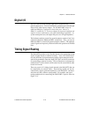
Timing Signal Routing
The DAQ-STC provides a very flexible interface for connecting timing
signals to other boards or external circuitry. Your AT E Series board
uses the RTSI bus for interconnecting timing signals between boards
and the Programmable Function Input (PFI) pins on the I/O connector
for connecting to external circuitry. These connections are designed to
enable the AT E Series board to both control and be controlled by other
boards and circuits.
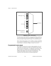
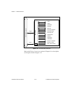
There are a total of 13 timing signals internal to the DAQ-STC that can
be controlled by an external source. These timing signals can also be
controlled by signals generated internally to the DAQ-STC, and these
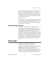
selections are fully software configurable. For example, the signal
routing multiplexer for controlling the CONVERT* signal is shown in
Figure 3-14.