


Chapter 3 Hardware Overview
AT-MIO/AI E Series User Manual 3-20
National Instruments Corporation
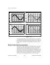
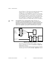
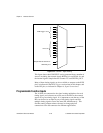
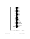
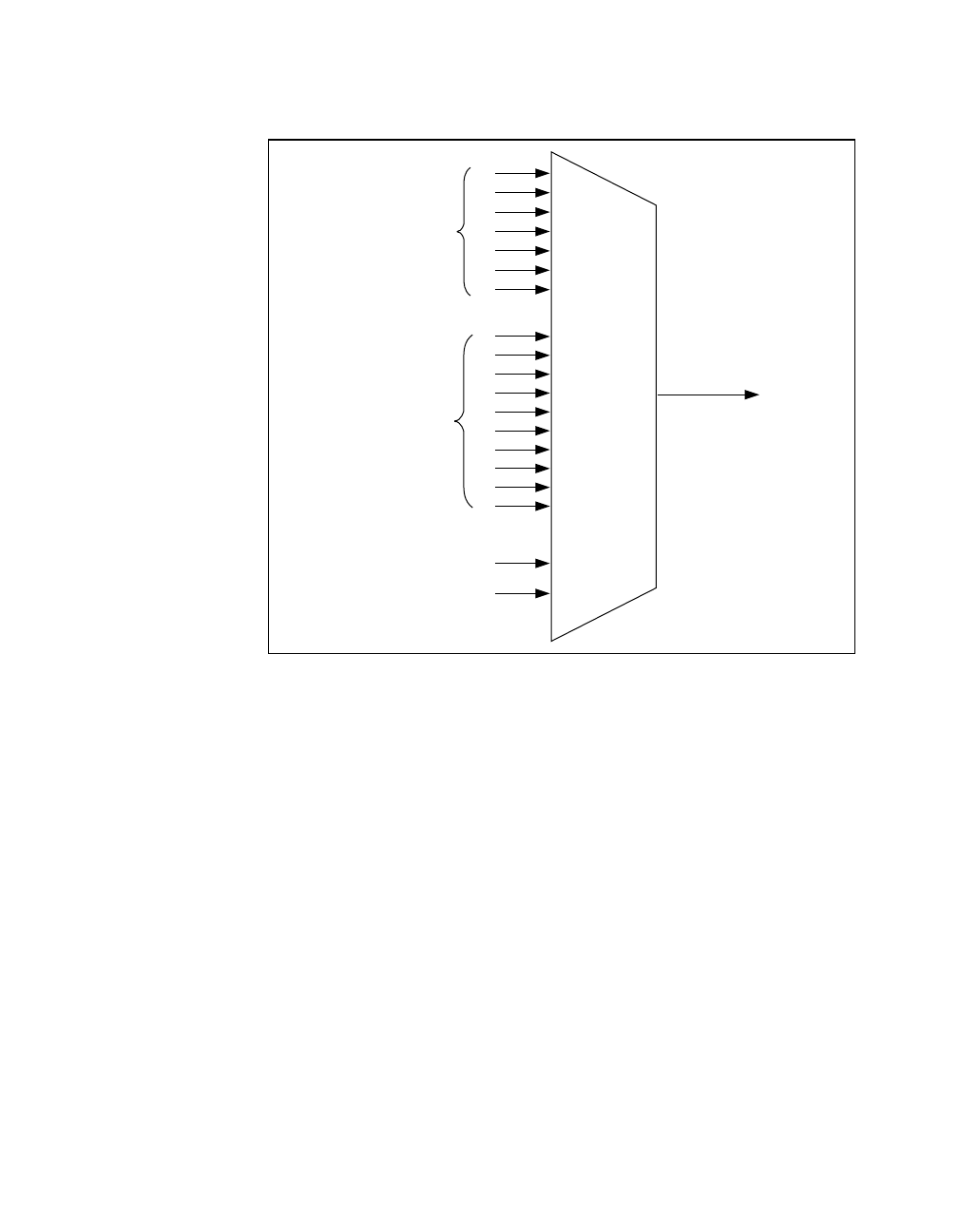
Figure 3-14. CONVERT* Signal Routing
This figure shows that CONVERT* can be generated from a number of
sources, including the external signals RTSI<0..6> and PFI<0..9> and
the internal signals Sample Interval Counter TC and GPCTR0_OUT.
Many of these timing signals are also available as outputs on the RTSI
pins, as indicated in the RTSI Triggers section later in this chapter, and
on the PFI pins, as indicated in Chapter 4, Signal Connections.
Programmable Function Inputs
The 10 PFIs are connected to the signal routing multiplexer for each
timing signal, and software can select one of the PFIs as the external
source for a given timing signal. It is important to note that any of the
PFIs can be used as an input by any of the timing signals and that
multiple timing signals can use the same PFI simultaneously. This
flexible routing scheme reduces the need to change physical
connections to the I/O connector for different applications.
RTSI Trigger <0..6>
PFI<0..9>
CONVERT*
Sample Interval Counter TC
GPCTR0_OUT