


Chapter 2 Installation and Configuration
AT-MIO/AI E Series User Manual 2-4
National Instruments Corporation
16-bit DMA channels, which correspond to channels 5, 6, and 7 in an
ISA computer and channels 0, 1, 2, 3, 5, 6, and 7 in an EISA computer.
These selections are all software configured and do not require you to
manually change any settings on the board.
Interrupt Channel Selection
The AT E Series boards can increase bus efficiency by using an
interrupt channel. You can use an interrupt channel for event
notification without the use of polling techniques. AT E Series boards
can use interrupt channels 3, 4, 5, 7, 10, 11, 12, and 15. These selections
are all software configured and do not require you to manually change
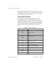
any settings on the board. The following tables provide information
concerning possible conflicts when configuring your AT E Series
board.
Table 2-1. PC AT I/O Address Map
I/O Address Range (Hex)
Device
100 to 1EF
—
1F0 to 1F8 IBM PC AT Fixed Disk
200 to 20F PC and PC AT Game Controller, reserved
210 to 213 PC-DIO-24 – default
218 to 21F —
220 to 23F Previous generation of AT-MIO boards – default
240 to 25F AT-DIO-32F – default
260 to 27F Lab-PC/PC+ – default
278 to 28F AT Parallel Printer Port 2 (LPT2)
279 Reserved for Plug and Play operation
280 to 29F WD EtherCard+ – default
2A0 to 2BF —
2E2 to 2F7 —
2F8 to 2FF PC, AT Serial Port 2 (COM2)