


Chapter 4 Signal Connections
AT-MIO/AI E Series User Manual 4-26
National Instruments Corporation
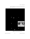
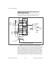
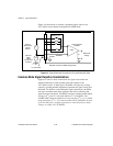
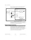
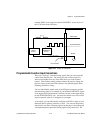
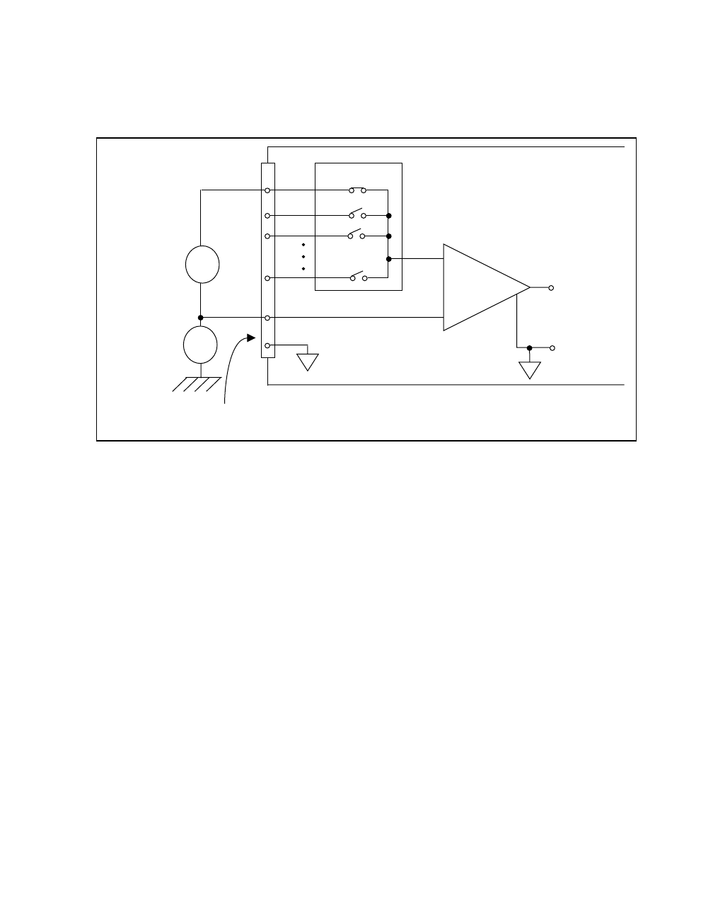
Figure 4-9 shows how to connect a grounded signal source to an
AT E Series board channel configured for NRSE mode.
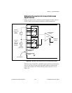
Figure 4-9. Single-Ended Input Connections for Ground-Referenced Signal
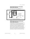
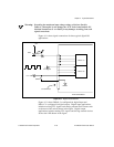
Common-Mode Signal Rejection Considerations
Figures 4-6 and 4-9 show connections for signal sources that are
already referenced to some ground point with respect to the
AT E Series board. In these cases, the PGIA can reject any voltage
caused by ground potential differences between the signal source and
the board. In addition, with differential input connections, the PGIA
can reject common-mode noise pickup in the leads connecting the
signal sources to the board. The PGIA can reject common-mode signals
as long as V
+
in
and V
-
in
are both within ±11 V of AIGND. The
AT-MIO-16XE-50 has the additional restriction that (V
+
in
+ V
-
in
) added
to the gain times (V
+
in
- V
-
in
) must be within ±26 V of AIGND. At gains
of 10 and 100, this is roughly equivalent to restricting the two input
voltages to within ±8 V of AIGND.
V
s
+
+
+
-
-
-
V
m
Measured
Voltage
ACH<0..15>
AIGND
Instrumentation
Amplifier
I/O Connector
AISENSE
V
cm
+
-
Selected Channel in NRSE Configuration
Common-
Mode
Noise
and Ground
Potential
Ground-
Referenced
Signal
Source
PGIA
Input Multiplexers