


Chapter 3 Hardware Overview
AT-MIO/AI E Series User Manual 3-16
National Instruments Corporation
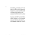
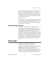
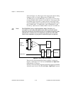
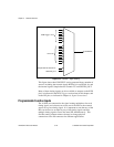
shown in Figure 3-8. The trigger-level range for the direct analog
channel is ±10 V in 78 mV steps for the AT-MIO-16E-1,
AT-MIO-16E-2, and AT-MIO-64E-3, and ±10 V in 4.9 mV steps
for the AT-MIO-16XE-10 and AT-AI-16XE-10. The range for the
post-PGIA trigger selection is simply the full-scale range of the
selected channel, and the resolution is that range divided by 256 for
the AT-MIO-16E-1, AT-MIO-16E-2, and AT-MIO-64E-3, and
divided by 4,096 for the AT-MIO-16XE-10 and AT-AI-16XE-10.
Note: The PFI0/TRIG1 pin is a high-impedance input. Therefore, it is
susceptible to cross-talk from adjacent pins, which can result in false
triggering when the pin is left unconnected. To avoid false triggering, make
sure this pin is connected to a low-impedance signal source (less than
10 kΩ source impedance) if you plan to enable this input via software.
Figure 3-8. Analog Trigger Block Diagram
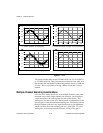
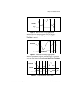
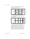
There are five analog triggering modes available, as shown in
Figures 3-9 through 3-13. You can set lowValue and highValue
independently in software.
In below-low-level analog triggering mode, the trigger is generated
when the signal value is less than lowValue. HighValue is unused.
Analog
Input
Channels
PFI0/TRIG1
PGIA
+
-
ADC
DAQ-STC
Analog
Trigger
Circuit
Mux