


Chapter 4 Signal Connections
AT-MIO/AI E Series User Manual 4-28
National Instruments Corporation
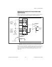
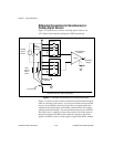
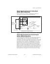
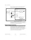
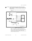
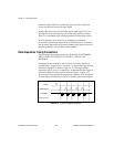
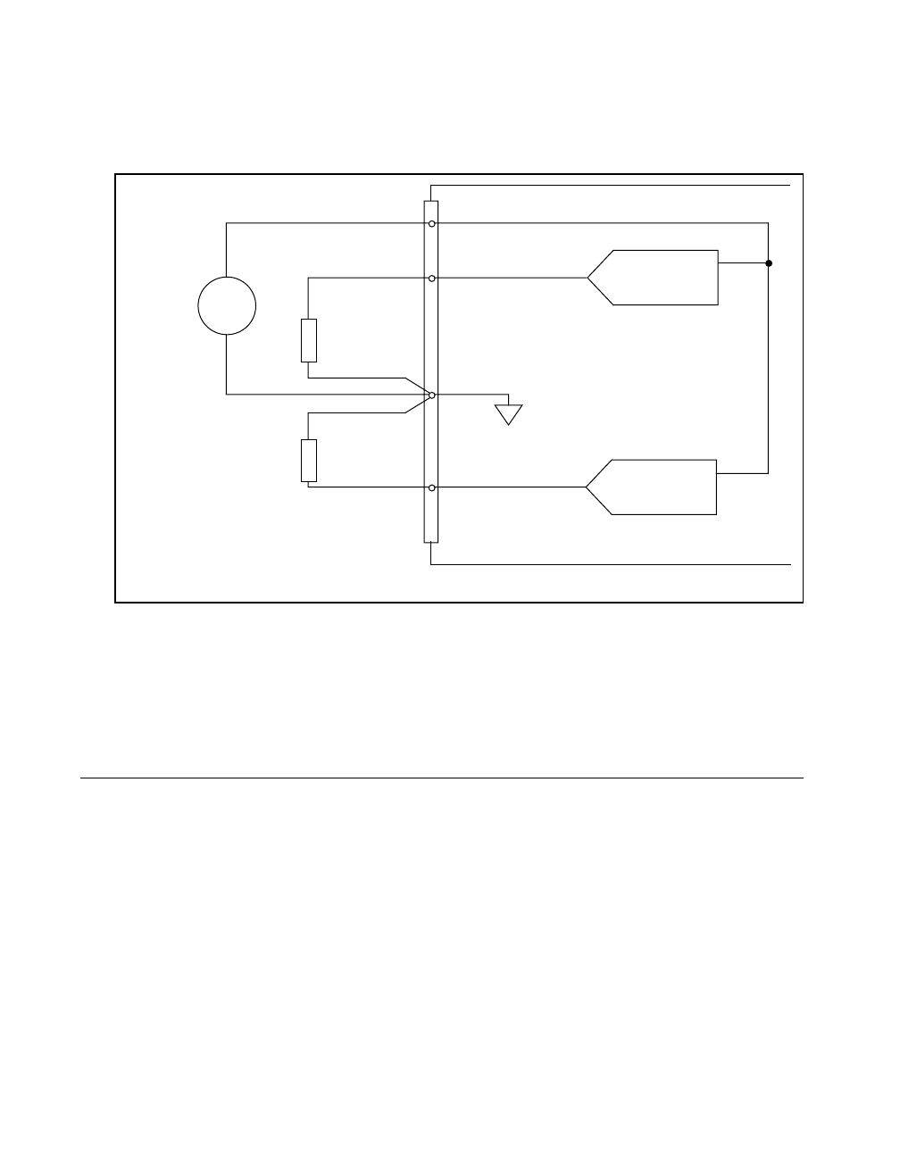
Figure 4-10 shows how to make analog output connections and the
external reference input connection to your AT E Series board.
Figure 4-10. Analog Output Connections
The external reference signal can be either a DC or an AC signal. The
board multiplies this reference signal by the DAC code (divided by the
full-scale DAC code) to generate the output voltage.
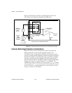
Digital I/O Signal Connections
The digital I/O signals are DIO<0..7> and DGND. DIO<0..7> are the
signals making up the DIO port, and DGND is the ground reference
signal for the DIO port. You can program all lines individually to be
inputs or outputs. The AT-MIO-16DE-10 has 24 additional DIO lines,
configured as three 8-bit ports: PA<0..7>, PB<0..7>, and PC<0..7>.
You can configure each port for both input and output in various
combinations, with some handshaking capabilities.
+
-
+
-
+
-
Channel 0
Channel 1
External
Reference
Signal
(Optional)
Load
Load
VOUT 0
VOUT 1
DAC1OUT
AO GND
DAC0OUT
EXTREF
Analog Output Channels
AT E Series Board
V
ref