


Chapter 4 Signal Connections
National Instruments Corporation 4-39 AT-MIO/AI E Series User Manual
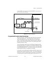
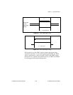
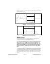
The CONVERT* pulses are masked off until the board generates the
STARTSCAN signal. If you are using internally generated
conversions, the first CONVERT* will appear when the onboard
sample interval counter reaches zero. If you select an external
CONVERT*, the first external pulse after STARTSCAN will generate
a conversion. The STARTSCAN pulses should be separated by at least
one scan period.
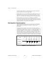
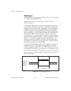
A counter on your AT E Series board internally generates the
STARTSCAN signal unless you select some external source. This
counter is started by the TRIG1 signal and is stopped either by software
or by the sample counter.
Scans generated by either an internal or external STARTSCAN signal
are inhibited unless they occur within a data acquisition sequence.
Scans occurring within a data acquisition sequence may be gated by
either the hardware (AIGATE) signal or software command register
gate.
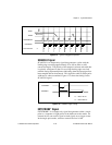
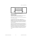
CONVERT* Signal
Any PFI pin can externally input the CONVERT* signal, which is
available as an output on the PFI2/CONVERT* pin.
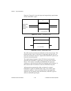
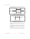
Refer to Figures 4-13 and 4-14 for the relationship of CONVERT* to
the data acquisition sequence.
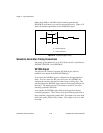
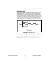
As an input, the CONVERT* signal is configured in the edge-detection
mode. You can select any PFI pin as the source for CONVERT* and
configure the polarity selection for either rising or falling edge. The
selected edge of the CONVERT* signal initiates an A/D conversion.
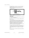
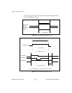
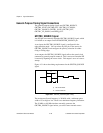
As an output, the CONVERT* signal reflects the actual convert pulse
that is connected to the ADC. This is true even if the conversions are
being externally generated by another PFI. The output is an active low
pulse with a pulse width of 50 to 100 ns. This output is set to tri-state
at startup.